[0008]The
advantage of the invention lies in the fact that the ability to directly electrically connect the synchronous motor to the first asynchronous machine, i.e. directly to the energy
supply network, provides the opportunity of supplying the synchronous motor with high currents, as must be supplied for the quasi-synchronous phase (QSP) entirely without a converter or if need be as a support for the converter. The fact that the synchronous motor is able to be electrically directly connected via the switchover device to the first asynchronous machine thus provides an option for bypassing the converter included anyway by the drive apparatus. This enables the converter to be designed for lower currents, so that overall a more cost-effective embodiment of the drive apparatus is produced. Previously the converter has functioned in each case as the interface between synchronous motor and energy
supply network, if necessary between the synchronous motor and an energy buffer downstream from the energy
supply network, so that the converter has had to be designed even for the high currents demanded at an almost
constant speed in stationary operation, which has led to a corresponding increase in price of the converter and thereby of the drive apparatus.
[0009]The
direct coupling of the first asynchronous machine to the synchronous motor during the first operating state has proved in trials to be a simple and robust as well as a cost-effective
system.
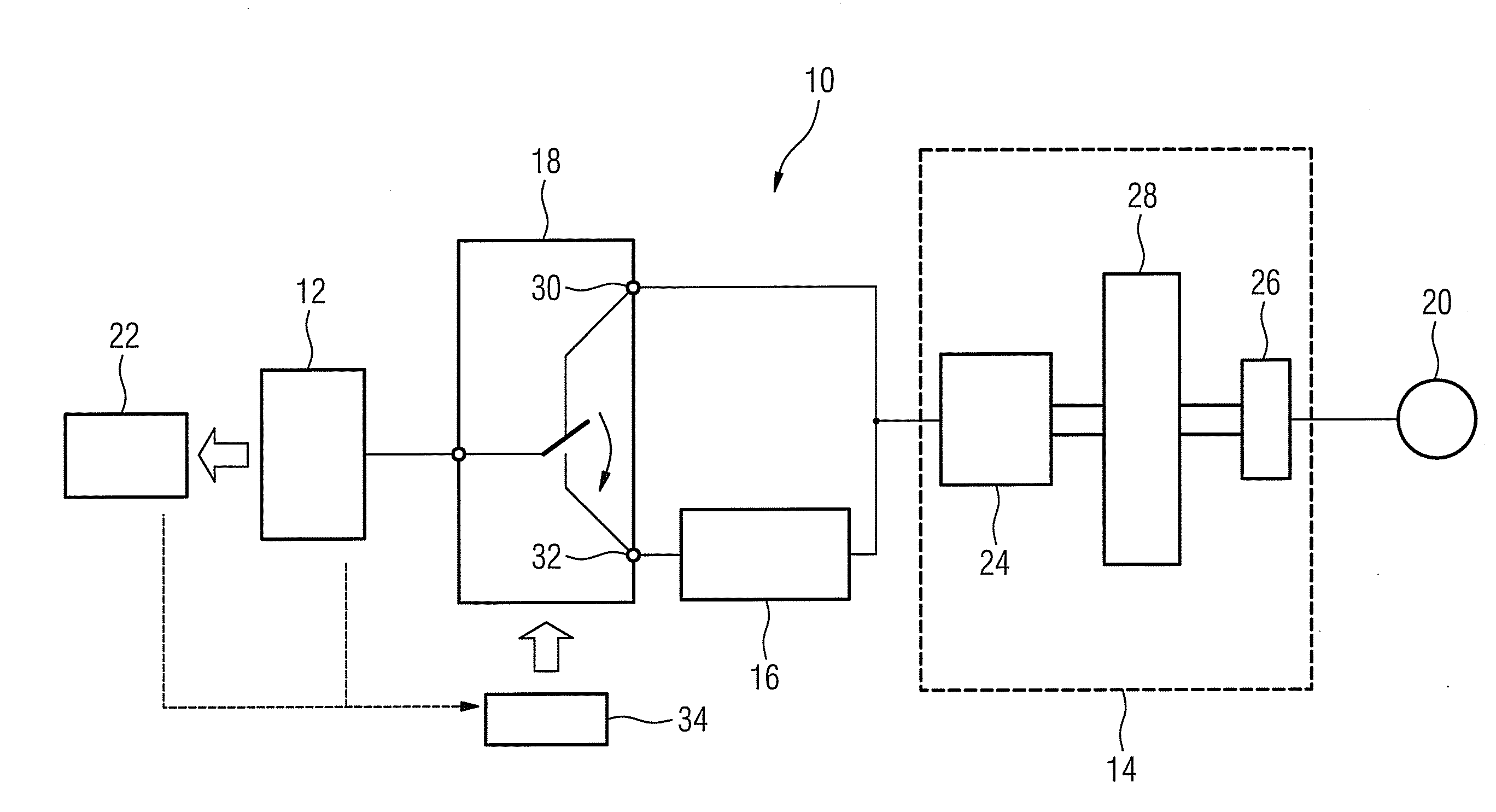
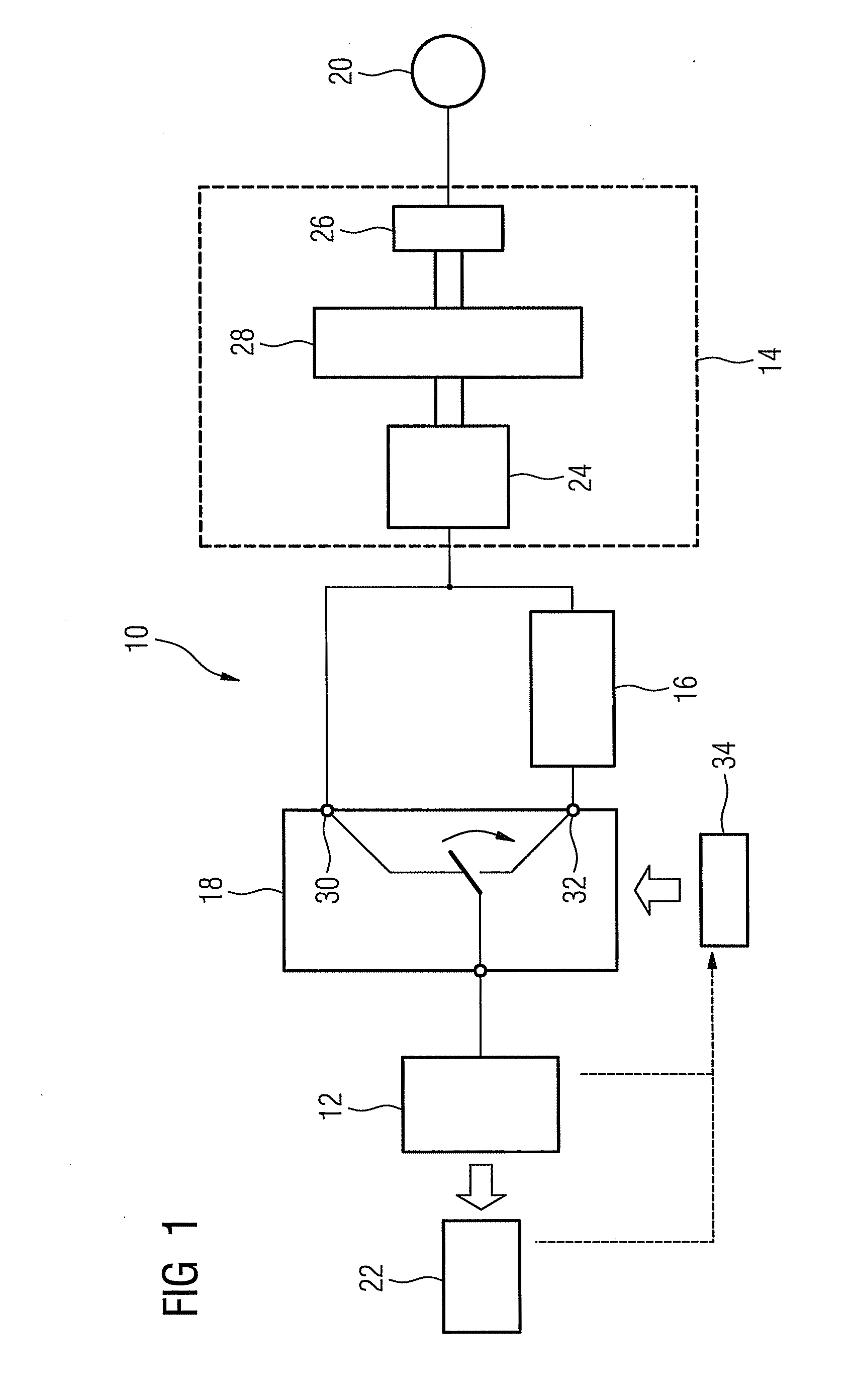
[0010]A preferred embodiment of the invention comprises at least one first asynchronous machine for connection of the drive apparatus to an energy supply network, at least one converter, connected on its input side to the first asynchronous machine, a switchover device comprising at least one first and one second input, the first input directly connected to the first asynchronous machine and the second input connected to the converter and at least one synchronous motor connected to the switchover device for feeding mechanical power to a production process, with the switchover device being configured so that during the operation of the drive apparatus the synchronous motor is supplied with energy during a first operating state (QSP) directly from the first asynchronous machine and during a second operating state (DP) from the first asynchronous machine by means of the converter.
[0011]The first operating state is in this case preferably an operating state with an essentially
constant speed and high
power demand, i.e. an operating state corresponding to the quasi-
stationary phase (QSP) mentioned above, and the second operating state is preferably an operating state with a variable speed and a lower demand for power compared to the first operating state, i.e. an operating state corresponding to the dynamic phase (DP) mentioned above.
[0012]The invention starts from the idea that a variable-speed power supply for the synchronous motor, especially in the first operating state (QSP), with high
power demand is not necessary, meaning that the converter does not have to be designed for this high
power demand. Instead the invention proposes a
coupling of the first asynchronous machine to the or to each synchronous motor which is connected to the respective production process that is able to be switched on and off with the switchover device during the first operating state. During this first operating state with largely constant drive speed and high power demand there can be a
direct coupling of the first asynchronous machine to the synchronous motor or, expressed in different terms, a bypassing of the converter. On the other hand, during the second operating state with a varying speed and lower power demand the synchronous motor will be supplied by the first asynchronous machine by means of the converter for example. In accordance with an alternate embodiment the converter can also be connected directly to the energy supply network. Since the demand for power during the second operating state is lower, the converter must consequently only be designed for the low power demand of the second operating state.
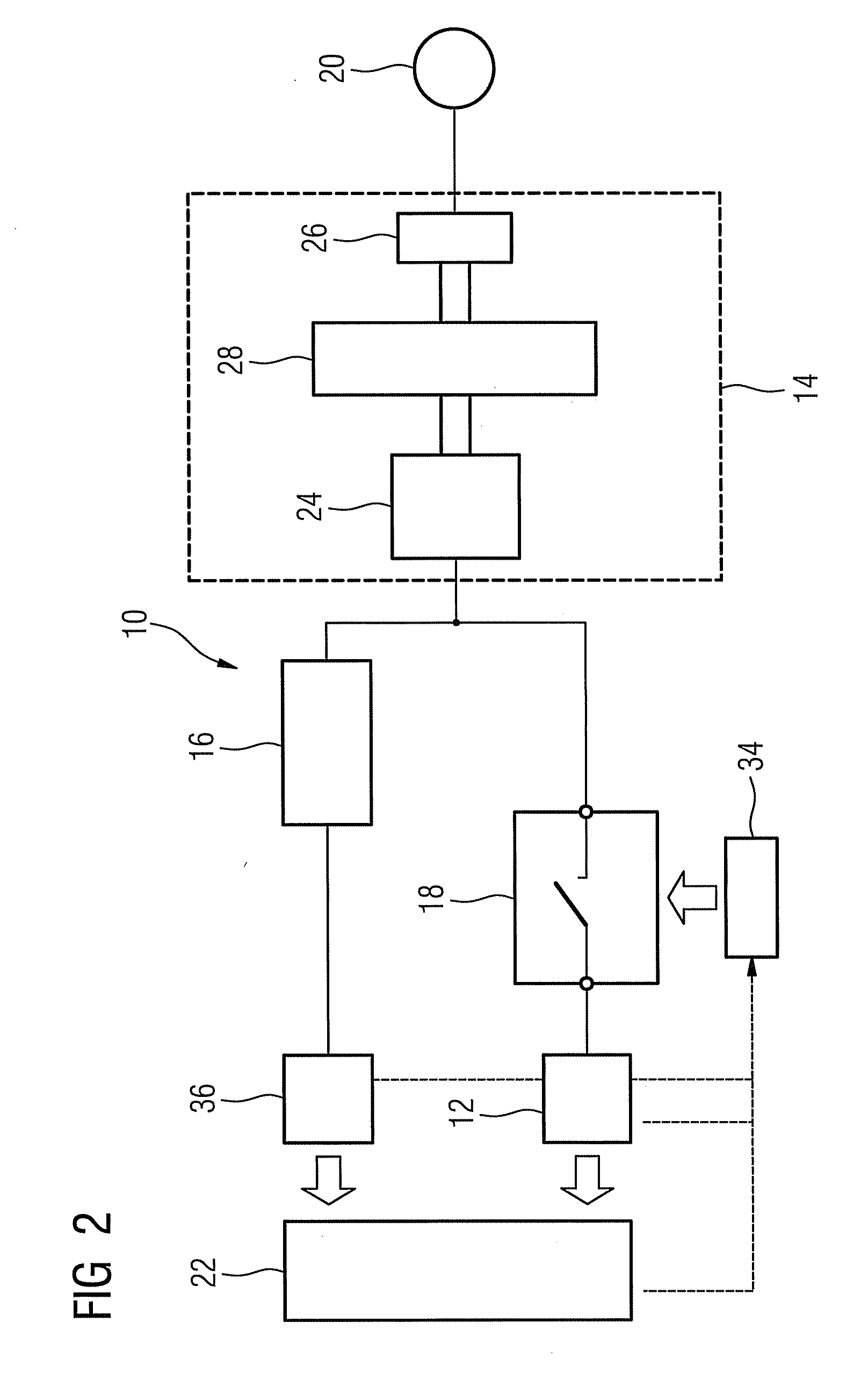
[0013]The above-mentioned alternate embodiment is characterized by the fact that the drive apparatus comprises two synchronous motors, with the first asynchronous machine being electrically connected directly via the switchover device to one of the two synchronous motors and being connected permanently via the converter electrically to the other synchronous motor. The synchronous motor able to be connected via the switchover device is thus intended for the first operating state, i.e. the quasi-
stationary phase (QSP). The synchronous motor connected via the converter on the other hand is intended for a second operating state, i.e. the dynamic phase (DP). This synchronous motor is dimensioned with the converter so that, the dynamic phase can be managed solely by this
system. During the entire dynamic phase or at least parts of such a dynamic phase the remaining part, i.e. the synchronous motor able to be activated via the switchover device, is electrically disconnected by the switchover device from the or from each first asynchronous machine. At the beginning of the first operating state (QSP) the synchronous motor connected via the switchover device is electrically connected via the latter to the or to each first asynchronous machine. The
mechanical load imposed by the process slows down the two synchronous motors, which leads to an oversynchronous operation of the first asynchronous machine. This means that the first asynchronous machine is operated as a generator and
mechanical energy (
kinetic energy of the mechanical energy buffer) is converted into electrical energy and supplied to the synchronous motor connected via the switchover device.
