Height control device for vehicle

Inactive Publication Date: 2009-08-06
TOYOTA JIDOSHA KK
View PDF5 Cites 5 Cited by
  • Summary
  • Abstract
  • Description
  • Claims
  • Application Information

AI Technical Summary

Benefits of technology

[0005]To cope with this problem, the seat surface of the driving seat may be displaced downward at an early stage of deceleration when the vehicle is decelerated, for example. At the early stage of deceleration, the center of gravity of the vehicle ascends, so as to increase the seat reaction force, thereby enhancing the deceleration felt by the driver. This may cause a possibility of falsely recognizing that the braking force is greater than the actual one, whereby the braking force may be fed insufficiently. Therefore, the seat is displaced downward at the early stage of deceleration, so as to restrain the seat surface from moving up even when the center of gravity of the vehicle ascends, thereby suppressing the increase in the seat reaction force. As a result, the driver can feel a deceleration similar to that acting on the vehicle.
[0007]It is therefore an object of the present invention to provide a vehicle altitude control apparatus which can provide the driver with a natural feel of deceleration at the time of decelerating the vehicle by adjusting the altitude of the driver with respect to the road surface.
[0009]While changing depending on the altitude of the vehicle, such as to become stronger as the altitude is higher, the feel of deceleration sensed by the driver has further been found to be affected not only by the altitude of the vehicle but also by the vehicle speed. Specifically, it has been found that the feel of deceleration becomes greater than the actual deceleration as the vehicle speed is higher. Based on such a finding, the vehicle altitude control apparatus in accordance with the present invention detects the vehicle speed and corrects the altitude of the driver with respect to the road surface according to the detected vehicle speed. This can provide the driver with a natural feel of deceleration.
[0010]Here, the target altitude setting means may be configured such as to correct the target altitude so that the amount of downward displacement of the target altitude becomes greater as the vehicle speed detected by the vehicle speed detecting means is higher.
[0013]When controlling the target altitude such as to make it lower as the vehicle speed is higher, the feel of deceleration is harder to obtain as the target altitude is lower, whereby the driver is harder to attain the feel of deceleration as the running speed is higher. This may cause a possibility of lowering the feel of deceleration with respect to a decelerating action as the vehicle runs faster, thereby making the driver feel a stronger sense of stroke. Therefore, when the amount of braking in the braking means is set greater as the vehicle speed detected by the vehicle speed detecting means is higher, the driver can be provided with a feel of deceleration proportional to the braking force.
[0015]When the ratio of altitude set with respect to the acceleration of the vehicle is thus determined according to the vehicle speed detected by the vehicle speed detecting means while the relationship between the altitude and the amount of operation of the brake operating means is held constant, the senses of difference between the braking force generated with respect to the amount of braking operation and the altitude of the driver can be reduced. This can lower the sense of discomfort with respect to the amount of braking operation given to the driver.

Problems solved by technology

Meanwhile, when the seating state of the driver changes during driving, the positional relationship between an operating device such as steering wheel or pedal and the driver changes, so as to alter its operability, which also makes the driver feel a sense of discomfort.
This may cause a possibility of falsely recognizing that the braking force is greater than the actual one, whereby the braking force may be fed insufficiently.

Method used


Image

  • Height control device for vehicle
  • Height control device for vehicle
  • Height control device for vehicle

Examples


Embodiment Construction

[0028]In the following, embodiments of the vehicle altitude control apparatus in accordance with the present invention will be explained with reference to the drawings. Explanations of the same members and constituents may be omitted.

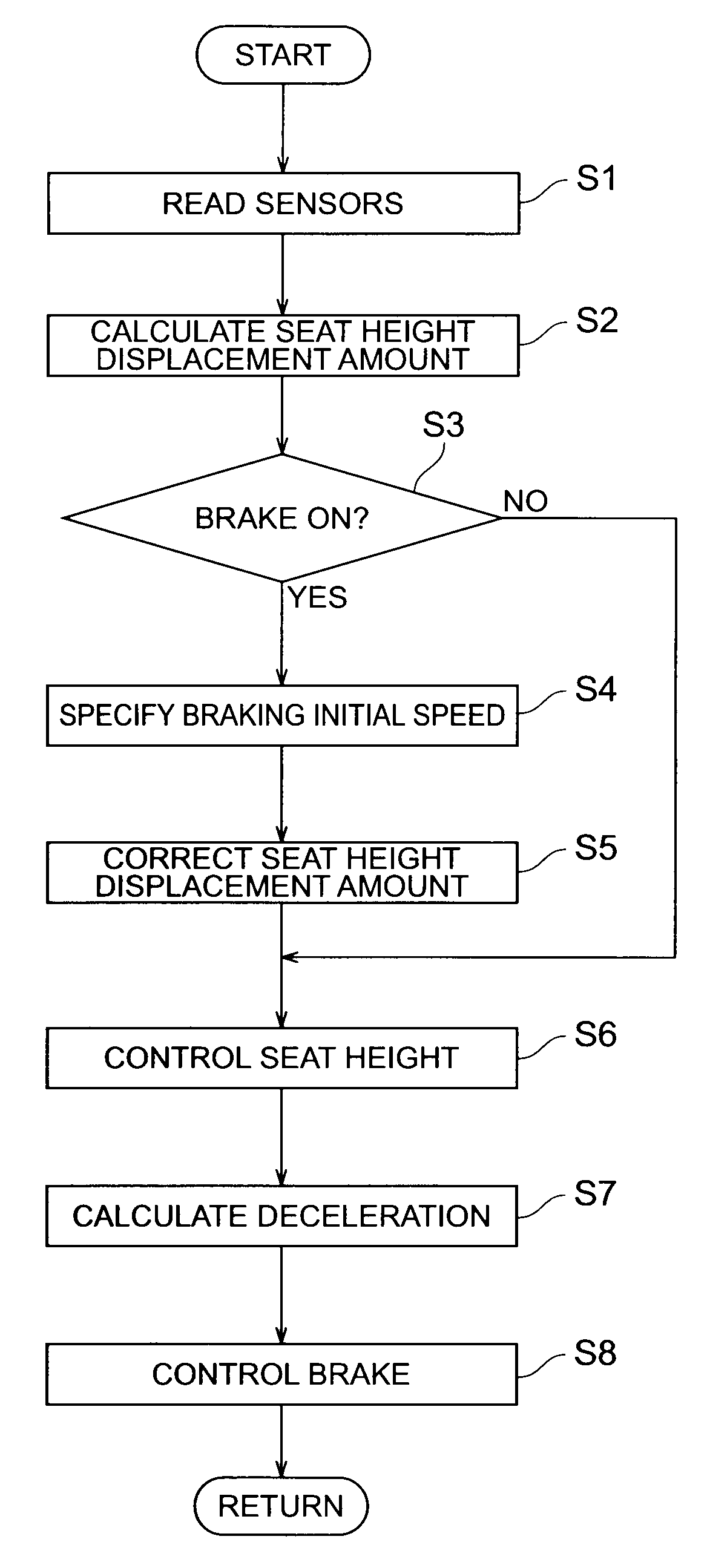
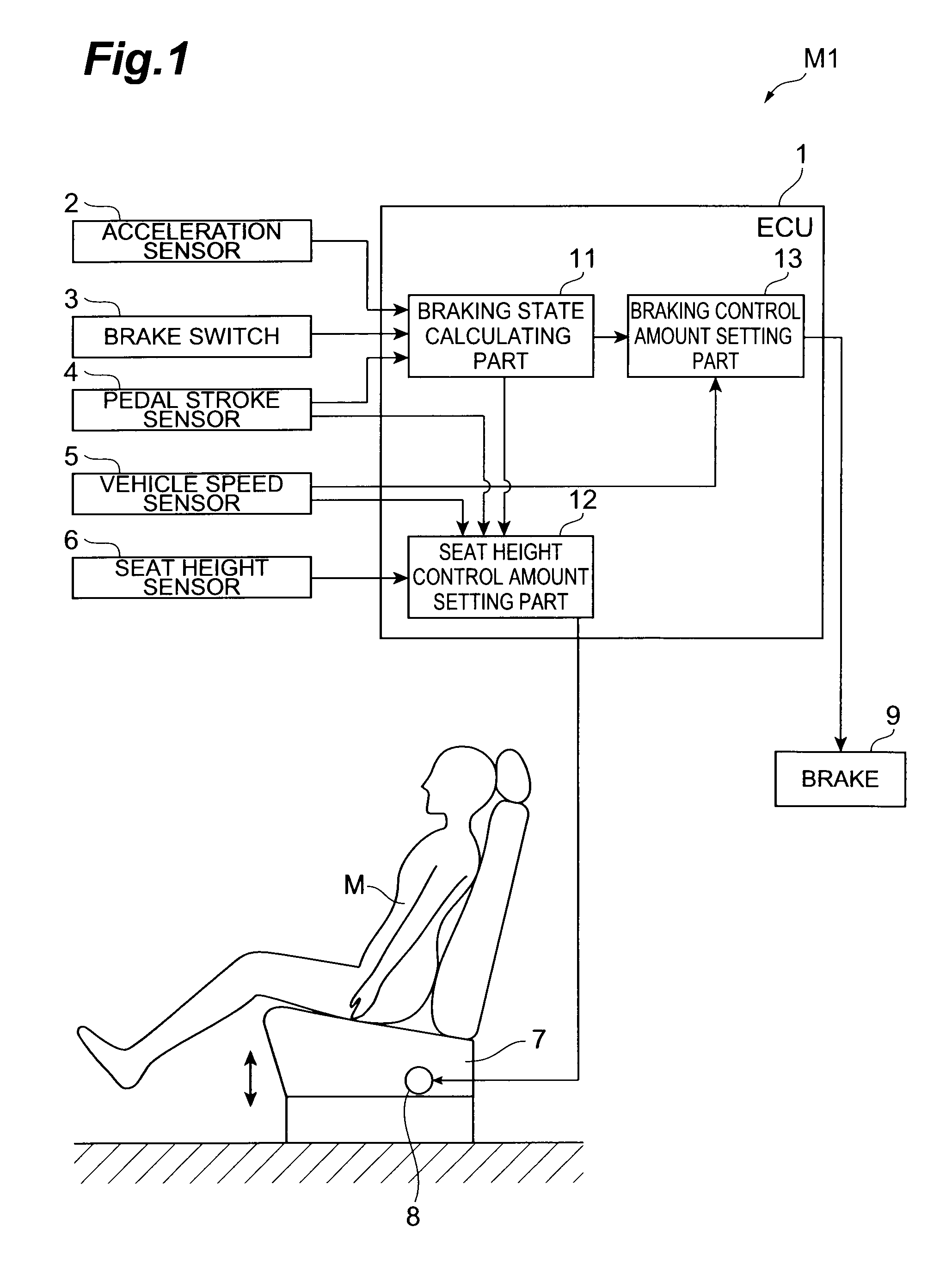
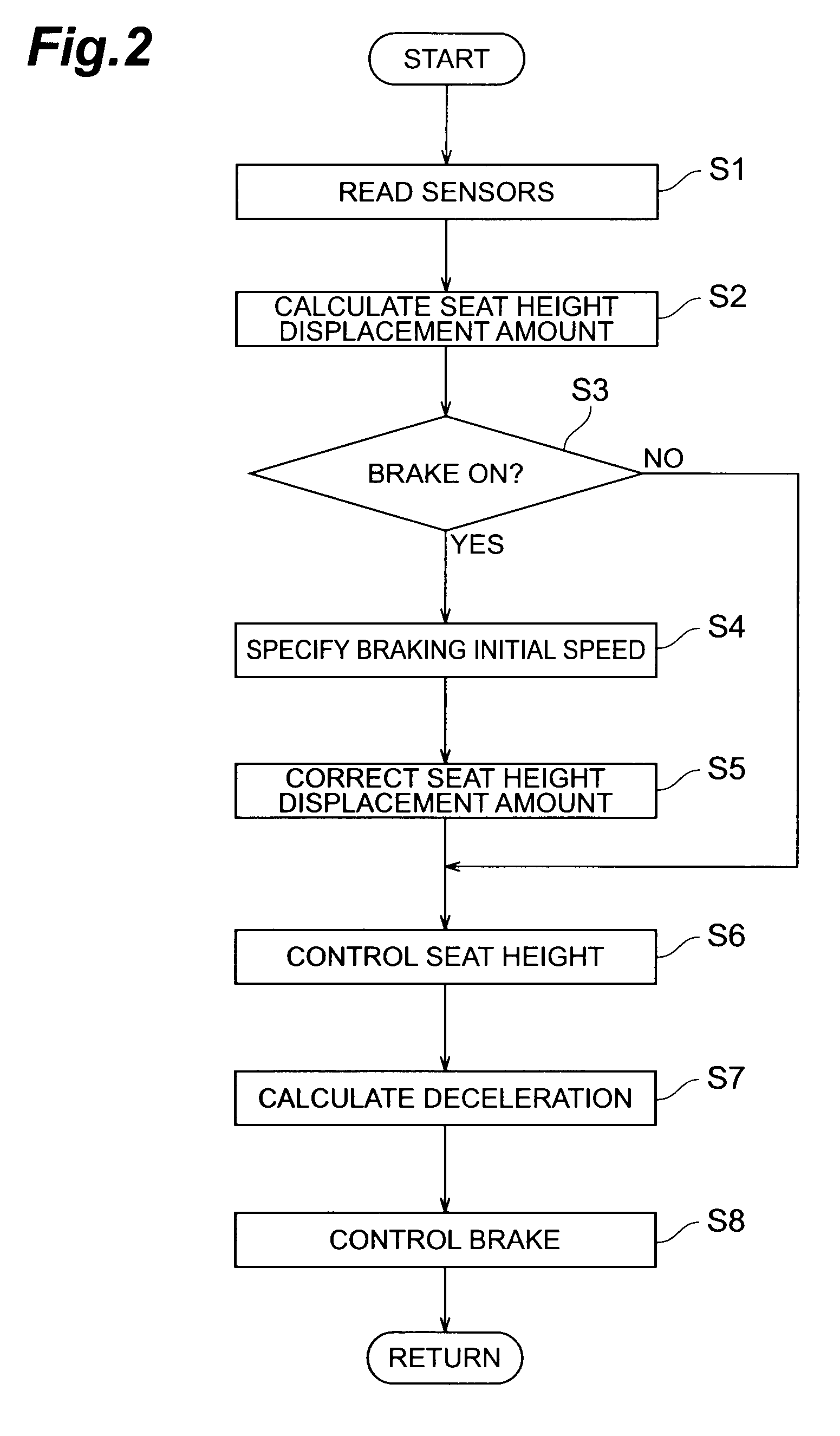
[0029]FIG. 1 is a block diagram showing the structure of a seat height control apparatus as the vehicle altitude control apparatus in accordance with an embodiment of the present invention, while FIG. 2 is a flowchart showing a controlling procedure in the seat height control apparatus in accordance with this embodiment. This embodiment adjusts the altitude of a driver with respect to the road surface by the seat height control in a driver's seat.

[0030]As shown in FIG. 1, the seat height control apparatus in accordance with this embodiment is provided in a vehicle M1 and includes an electronic control unit (hereinafter referred to as “ECU”) 1. The ECU 1 comprises a braking state calculating part 11, a seat height control amount setting part 12 which is ...


PUM


Abstract

A seat height control amount setting part determines a target seat height displacement amount according to a deceleration outputted from a braking state calculating part. The deceleration is corrected according to the vehicle speed of a vehicle, and the target seat displacement amount is set such that the seat height becomes lower as the vehicle speed is higher. While correcting the target seat height displacement amount, a target deceleration with respect to the amount of operation of a brake pedal is corrected. The target deceleration is corrected such that the target deceleration with respect to the amount of operation of the brake pedal becomes greater as the vehicle speed is higher.

Description

TECHNICAL FIELD[0001]The present invention relates to a vehicle altitude control apparatus for controlling an altitude of a driver in a vehicle with respect to a road surface.BACKGROUND ART[0002]Techniques have been known for changing the position and altitude of the seat surface and the like of a driver's seat in a vehicle according to the body shape and likings of the driver. They aim at improving the driver's feel of seating by utilizing such a driver's seat. On the other hand, as performances of vehicles have been improving, high-speed running and operating characteristics have been made better than those conventionally attained. As a result, the acceleration, deceleration, rolling force, and the like acting on passengers have been becoming greater than conventional ones. As the speed and posture of the vehicle change, the inertial force acting on the passengers may alter the state of seating of the passengers, so as to cause a sense of discomfort in the feel of seating, thereby...

Claims


Application Information

Patent Timeline
IPC IPC(8): B60N2/16
CPCB60G17/0164B60G2400/106B60G2400/204B60G2400/25B60G2400/39B60T13/662B60N2/0244B60N2/0276B60N2/16B60T8/3255B60G2500/30
Inventor ISONO, HIROSHI
Owner TOYOTA JIDOSHA KK
Why Eureka
Try Eureka