
Process for producing a purified synthesis gas stream

a technology of purified synthesis and gas stream, which is applied in the direction of combustible gas purification/modification, gasifier mechanical details, hydrogen separation using liquid contact, etc., can solve the problem of removing a part of the methanol inventory from the circulating methanol, and achieve the effect of avoiding the buildup of contaminants

Inactive Publication Date: 2009-07-23
SHELL OIL CO
View PDF3 Cites 26 Cited by
  • Summary
  • Abstract
  • Description
  • Claims
  • Application Information

AI Technical Summary

Benefits of technology

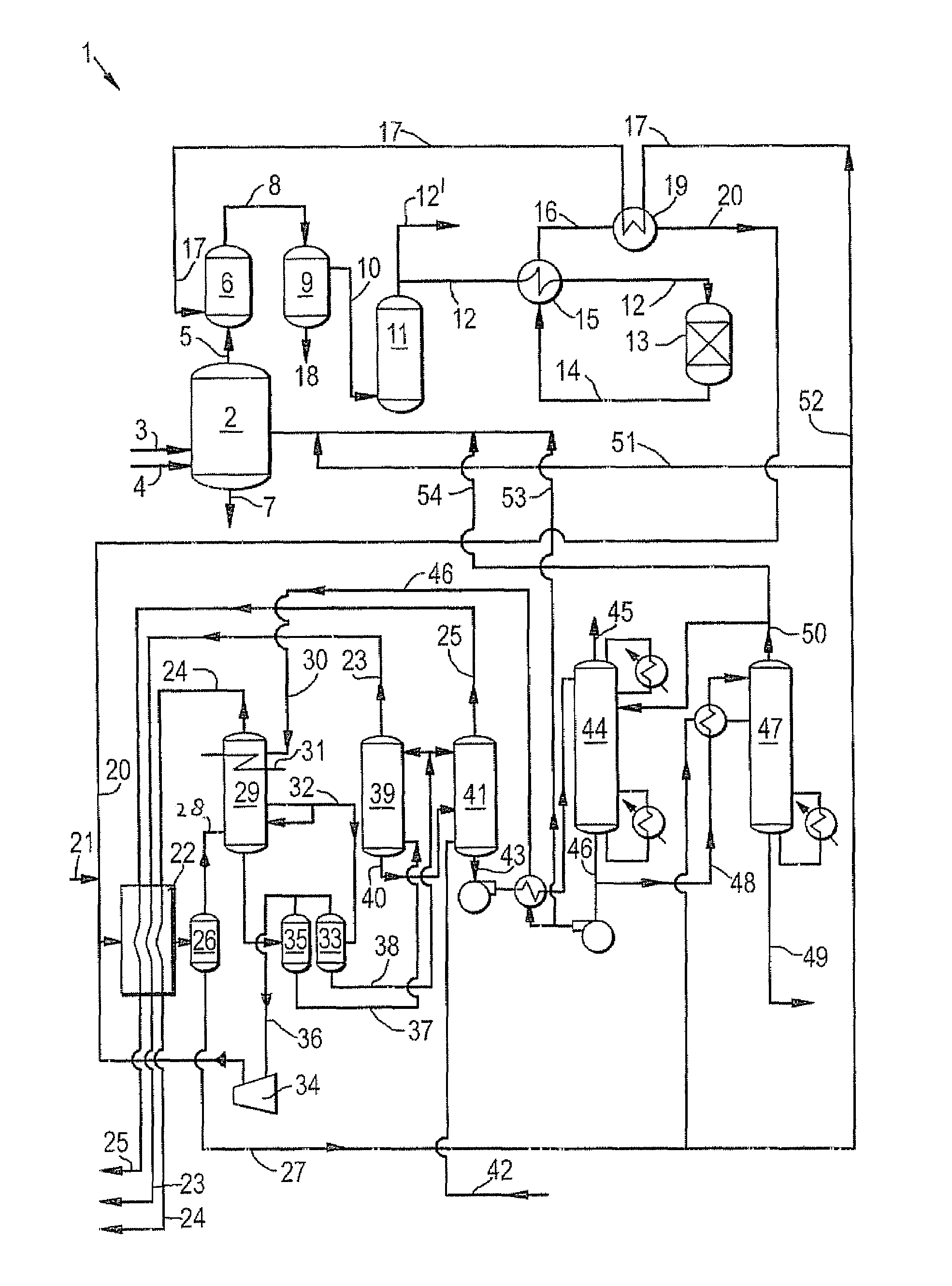
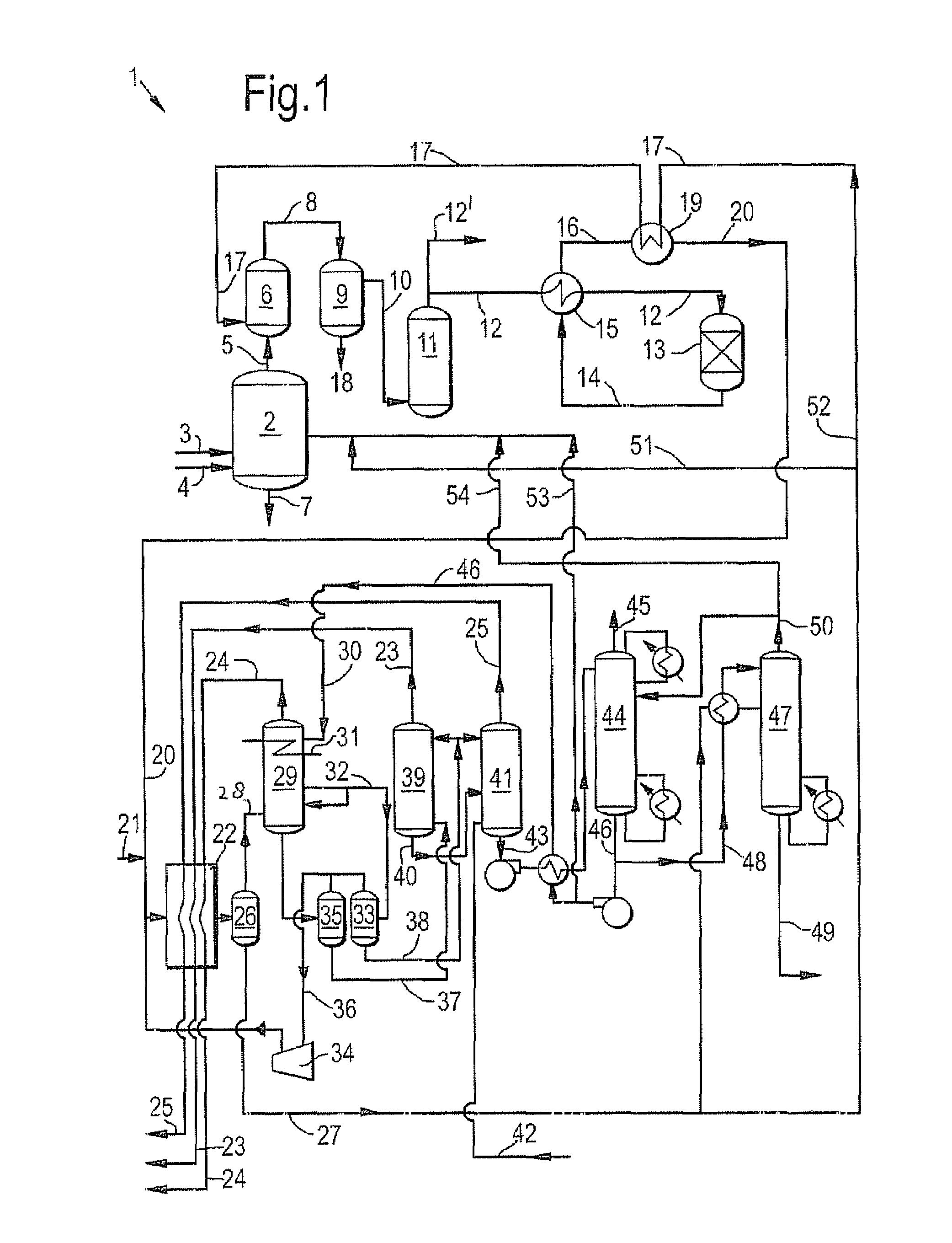
[0011](b) mixing the synthesis gas and methanol and reducing the temperature of said mixture and separating a liquid methanol-water mixture from a cooled gaseous synthesis gas,
[0016]Applicants found that by recycling part of the methanol as present in the methanol-water mixture obtained in step (b) to step (a) the build up of contaminants is avoided. At the same time additional synthesis gas is prepared from this waste stream when methanol is converted by an endothermic reaction to CO and H2.

Problems solved by technology

An issue with the above process is that part of the methanol inventory has to be removed from the circulating methanol to avoid a build-up of certain contaminants, such as for example ammonia, cyanide, unidentified sulphur species and trace metals.

Method used


Image

  • Process for producing a purified synthesis gas stream
  • Process for producing a purified synthesis gas stream
  • Process for producing a purified synthesis gas stream

Examples


Embodiment Construction

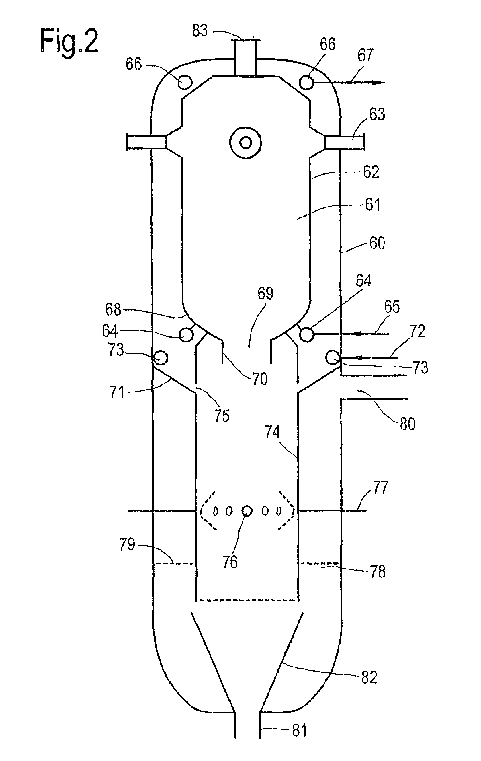
[0020]In step (a) a carbonaceous feedstock is subjected to partial oxidation with a molecular oxygen comprising gas. The partial oxidation is preferably performed at a temperature of between 1000 and 1800° C. and more preferably at a temperature between 1200 and 1800° C. The pressure at which partial oxidation is performed is preferably between 0.3 and 12 MPa and more preferably between 3 and 10 MPa. When an ash containing feedstock is used the temperature conditions are so chosen that a slag layer will form on the interior of the reactor vessel in which the partial oxidation takes place.

[0021]The carbonaceous feedstock is preferably coal, for example anthracite, brown coal, bitumous coal, sub-bitumous coal, and lignite. Examples of alternative carbonaceous feedstocks are petroleum coke, peat and heavy residues as extracted from tar sands or the asphalt fraction as separated from said residues in a de-asphalting process Residues from refineries such as residual oil fractions boiling...


PUM

PropertyMeasurementUnit
temperatureaaaaaaaaaa
pressureaaaaaaaaaa

Abstract

A process for producing a purified synthesis gas stream from a carbonaceous feedstock, the process comprising the steps of(a) partial oxidation of the carbonaceous feedstock with a molecular oxygen comprising gas to obtain a synthesis gas comprising water, hydrogen sulphide, and carbon dioxide besides the main constituents carbon monoxide and hydrogen,(b) mixing the synthesis gas and methanol and reducing the temperature of said mixture and separating a liquid methanol-water mixture from a cooled gaseous synthesis gas,(c) contacting the cooled synthesis gas obtained in step (b) with methanol to decrease the content of hydrogen sulphide and carbon dioxide in the synthesis gas, thereby obtaining a rich methanol stream comprising hydrogen sulphide and carbon dioxide and a synthesis gas stream depleted in hydrogen sulphide and carbon dioxide;(d) regenerating the rich methanol stream of step (c) by separating from the rich methanol a carbon dioxide fraction and a hydrogen sulphide fraction to obtain lean methanol, which lean methanol is used as methanol in step (b) and / or (c), and wherein(e) part of the methanol in the methanol-water mixture obtained in step b) is isolated and reused in step (b) and / or (c) and wherein,(f) another part of the methanol in the methanol-water mixture obtained in step (b) is recycled to step (a) under conditions such that methanol is converted into carbon monoxide and hydrogen.

Description

[0001]This patent application claims the benefit of European patent application No. 07121140.3, filed Nov. 20, 2007 and U.S. Provisional Application 60 / 991,160, filed Nov. 29, 2007, both of which are incorporated herein by referenceTECHNICAL FIELD OF THE INVENTION[0002]The present invention relates to a process for producing a purified synthesis gas stream from a carbonaceous feedstock.BACKGROUND OF THE INVENTION[0003]It is known to prepare purified synthesis gas from a carbonaceous feedstock by first performing a partial oxidation, also referred to as gasification, of the feedstock followed by a scrubbing step, a CO shift step and a CO2 and H2S removal step. Such a process is described in Gasification Technology Counsel (GTC 2004) Conference paper called “Synthesis Gas Purification in Gasification to Ammonia / Urea Complex” of John Y Mak and others (http: / / www.gasification.org / Presentations / 2004.htm). In FIG. 5 of this paper an integrated process is described wherein a coal slurry fe...

Claims


Application Information

Patent Timeline
Patent Type & Authority Applications(United States)
IPC IPC(8): C10J3/46
CPCC01B3/36Y02E50/18C01B2203/0255C01B2203/0415C01B2203/0475C01B2203/0485C01B2203/148C10J3/485C10J3/84C10J3/845C10J2200/09C10J2200/152C10J2300/0916C10J2300/093C10J2300/1618C10J2300/1634C10J2300/1659C10J2300/1665C10J2300/1807C10J2300/1846C10K1/004C10K1/005C10K1/101C10K1/14C01B3/52Y02P20/145Y02E50/10
Inventor SMIT, CORNELIS JACOBUSZANDER, JAN VOLKERT
Owner SHELL OIL CO
Learn More