
Solar Enclosure Apparatus and Method

Inactive Publication Date: 2009-07-09
MEININGER JUSTIN +1
View PDF4 Cites 8 Cited by
  • Summary
  • Abstract
  • Description
  • Claims
  • Application Information

AI Technical Summary

Benefits of technology

[0009]The objective of the present invention is to provide a layered panel and an assembled habitat enclosure system comprised of an assembly of said panels with solar energy panels to absorb solar energy and transform it into electric energy via a solar energy to electric energy switching device, thereby providing a power supply. For achieving the above objective, the invention combines new light weight and structurally flexible organic panels, more particularly described below, said panels having three layers, said layers comprising an exterior solar photovoltaic layer, a light weight and structurally flexible middle layer of thin batteries, and an interior layer of thin organic structurally flexible light emitting diode (“OLED”) film, said OLED's comprising the actual interior wall of said habitat enclosure system. A microprocessor based integrated circuit energy management system providing monitoring, safe and proper functioning of the electrical energy produced, stored and distributed for the individual multi-layered panels and / or the entire panel assembled habitat enclosure system.
[0010]On the exterior layer of the layered panels, this invention uses new lightweight, structurally flexible, solar cells made of organic materials; i.e. cells based on polymers with carbon bonds. Currently, organic semi-conductors include not only polymers [molecular mass greater than 10,000 AMU (atomic mass units)], but also small molecules (molecular mass less than a few thousand AMU), and dendrimers (molecular masses between the polymers and small molecules). Organic solar cells work differently from conventional inorganic semiconductor solar cells. Light absorbed by an inorganic semiconductors produce free charge carriers—electrons and holes—that are transported separately through the semiconductor material. In an organic solar cell, however, light absorption produces excitons, electron-hole pairs that are bound together and hence not free to move separately. To generate free charge carriers, the excitons must be dissociated. This can happen in the presence of high electric fields, at a defect site in the material, or usually, at the interface between two materials that have a sufficient mismatch in their energy levels. Thus, an organic solar cell can be made with the following layered structure: positive electrode / electron donor / electron acceptor / negative electrode. An exciton created in either the electron donor or electron acceptor layer can diffuse to the interface between the two, leading to electron transfer from the donor material to the acceptor, or hole transfer from the acceptor to the donor. The negatively charged electron and the positively charged hole is then transported to the appropriate electrode. Organic materials are diverse and versatile, offering endless possibilities for improving a wide range of properties such charge generation, separation, molecular mass, wettability between organic molecules and inorganic material, the ability to harvest light efficiently in different parts of the solar spectrum, especially the infrared, molecular energy levels, rigidity, and molecule-to-molecule interactions. Different organic molecules can be combined with one another, or with inorganic materials in many unique formulations. One major advantage of organic solar panels is the low cost involved in manufacture. Organic molecules are cheap to make, they can have very high light absorbing capacity so that films as thin as several hundred nanometres would be sufficient for the purpose. Organic materials are compatible with plastic and other flexible substrates; and devices can therefore be fabricated with low-cost, high throughput printing techniques that consume less energy and require less capital investment than silicon-based devices and other thin-film technologies. Consequently, organic solar cells do not need to have conversion efficiencies as high as thin-film inorganic solar cells to become competitive in the market. Another advantage of these cells is that they are good for high latitudes. They do not have the reflectivity of inorganic materials such as silicon, which allows them to have greater conversion efficiency when the sun is at high angles relative to the cell.

Problems solved by technology

In an organic solar cell, however, light absorption produces excitons, electron-hole pairs that are bound together and hence not free to move separately.

Method used


Image

  • Solar Enclosure Apparatus and Method
  • Solar Enclosure Apparatus and Method
  • Solar Enclosure Apparatus and Method

Examples


Embodiment Construction

[0018]Detailed descriptions of the preferred embodiments are provided herein. It is to be understood, however, that the present invention may be embodied in various forms. Therefore, specific details disclosed herein are not to be interpreted as limiting, but rather as a basis for the claims and as a representative basis for teaching one skilled in the art to employ the present invention in virtually any appropriately detailed system, structure or manner.

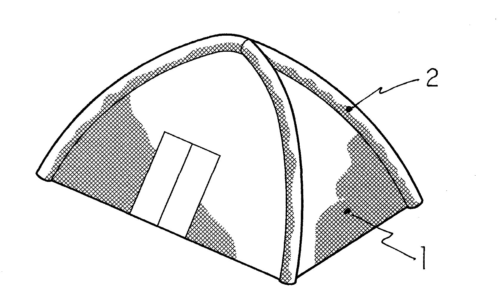
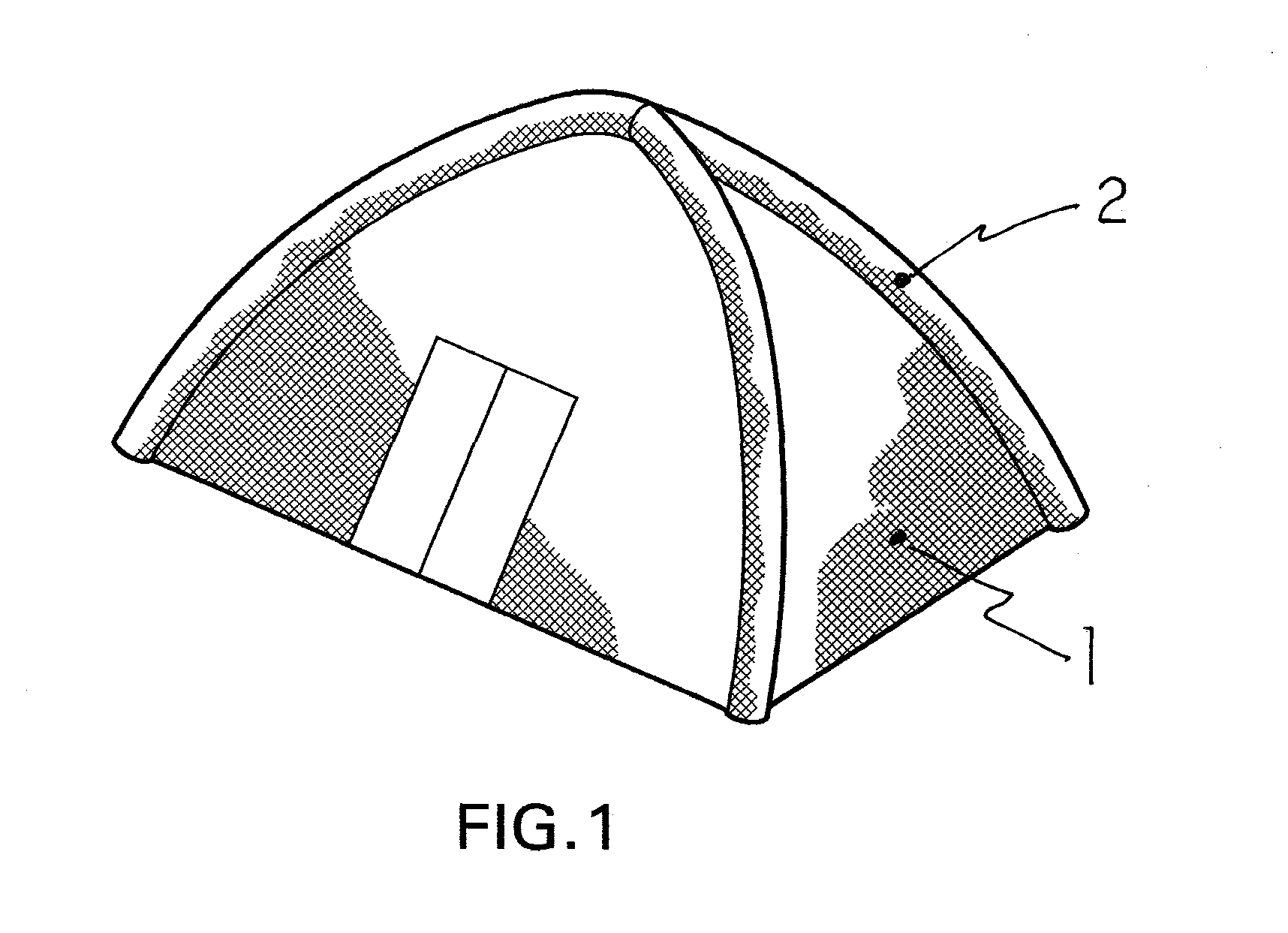
[0019]FIG. 1 is perspective view of one geometric confguration and embodiment for the invention. It comprises an assembled habitat enclosure system of layered panels, said panels combining new light weight and structurally flexible organic panels, said panels having three layers, said layers comprising an exterior solar photovoltaic layer, a light weight and structurally flexible middle layer of thin batteries, and an interior layer of thin organic structurally flexible light emitting diode (“OLED”) film, said OLED's comprising the ...


PUM


Abstract

Solar energy has been used for generating electricity by using silicon based solar cells for years by mounting them on the outside surfaces of buildings. These cells have also been used for outdoor recreation, by mounting said silicon solar panels adjacent to a tent. To store the electrical energy produced by the silicon based cells, large, cumbersome battery systems were used. To provide needed working light inside of these solar powered building enclosures, the occupant needed separate light fixtures. This invention combines new light weight structurally flexible organic panels, said panels having three layers, said layers comprising an exterior solar photovoltaic layer, a middle layer of thin batteries and an interior layer of thin organic structurally flexible light emitting diode (“OLED”) film, said OLED's comprising the interior wall of said enclosure system. There is a microprocessor based circuit monitoring and management of the electrical energy produced, stored and used.

Description

CROSS REFERENCE TO RELATED APPLICATIONS[0001]Not Applicable.STATEMENT REGARDING FEDERALLY SPONSORED RESEARCH OR DEVELOPMENT[0002]Not ApplicableDESCRIPTION OF ATTACHED APPENDIX[0003]Not ApplicableBACKGROUND OF THE INVENTION[0004]1. Field of the Invention[0005]The present invention relates to an solar energy powered habitat enclosure system, capable of being used as a human and / or animal portable or permanent habitat, said system comprising an assembly of individual layered panels, wherein the exterior and interior layer within said panels, are made substantially of structurally flexible organic based materials, including, the exterior layer being for photovoltaic solar energy collection, the middle layer for resultant electrical energy battery storage, the interior layer for light emitting diode illumination, and a microprocessor based integrated circuit to monitor and manage said enclosure system.[0006]2. Description of the Prior Art[0007]Solar energy has been used for generating el...

Claims


Application Information

Patent Timeline
IPC IPC(8): H01L31/048
CPCE04H1/1205E04H2015/201H01L31/0392H02S30/20H01M10/465Y02B10/12Y02E10/50H01M10/052H01L31/03926Y02B10/10Y02E60/10
Inventor MEININGER, JUSTINMILLER, STEVEN J.
Owner MEININGER JUSTIN
Learn More