
Remote terminal emulation system and method

a terminal and remote terminal technology, applied in the field of remote terminal emulation system, can solve the problems of data transmission safety, unsuitable computer control system type between different areas of a telecommunication network, loss of transmitted data,

Inactive Publication Date: 2005-09-22
ICP ELECTRONICS
View PDF1 Cites 4 Cited by
  • Summary
  • Abstract
  • Description
  • Claims
  • Application Information

AI Technical Summary

Benefits of technology

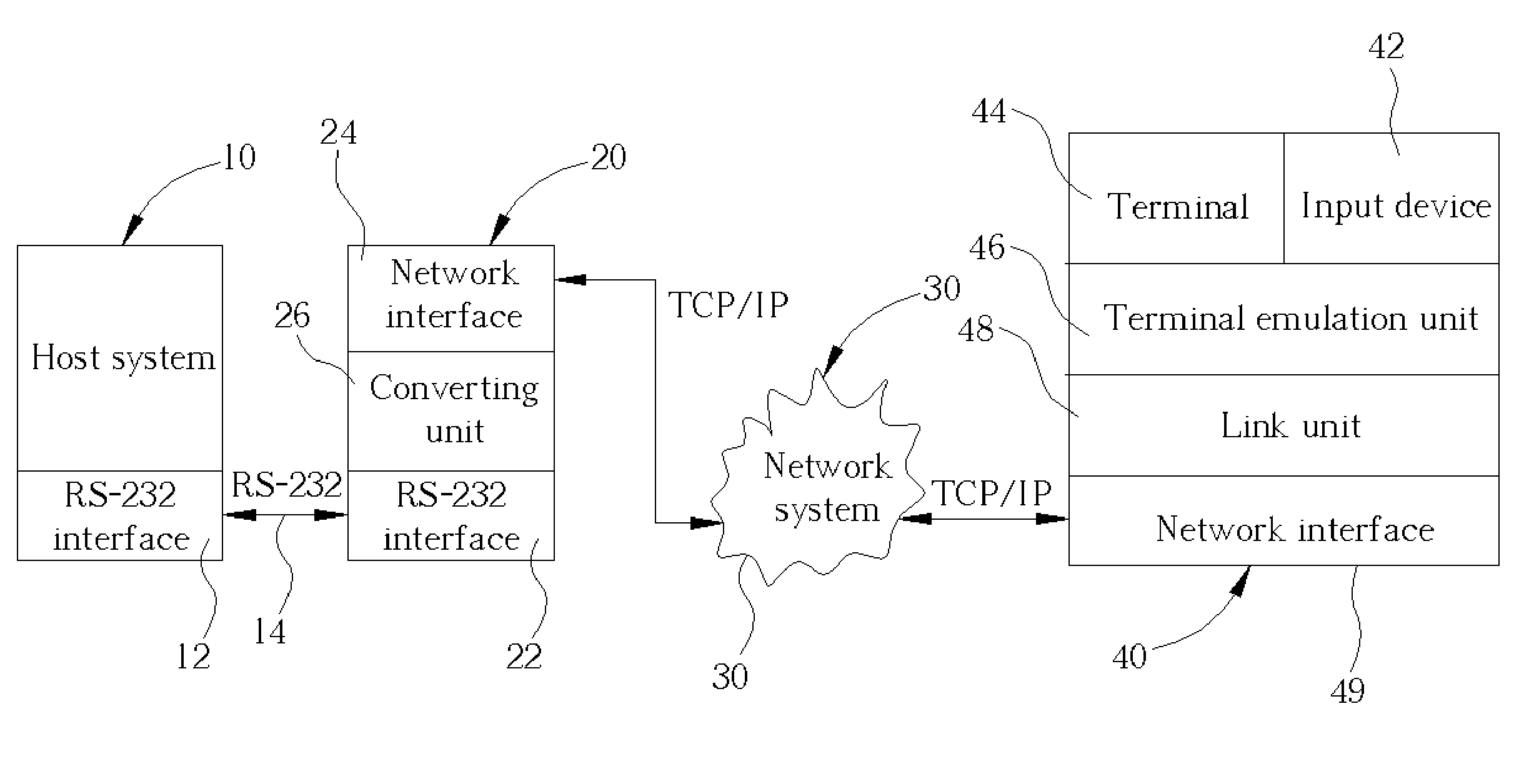
[0007] According to the claimed invention, a remote terminal emulation system is disclosed for timely presenting data in serial signal form outputted from a host system on a terminal of a remote computer system via a network system. The remote terminal emulation system includes an information converting apparatus. The information converting apparatus includes a serial signal interface electrically connected to the remote computer system for transmitting the data in serial signal form, a network interface electrically connected to the network system for transmitting network packets, and a converting unit for converting data between serial signal form and network packet form. The remote terminal emulation system further includes a terminal emulation unit installed inside the remote computer system for presenting the data in serial signal form on the terminal of the remote computer system according to a terminal emulation method so as to provide a remote-control function when the remote computer system receives the data in network packet form from the host system via the network system.

Problems solved by technology

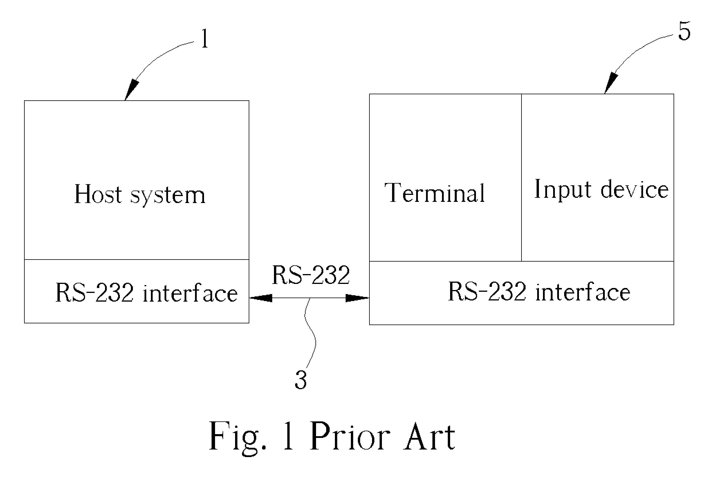
However, transmitted data might be lost due to an excessively long communication distance, so in general the cable 3 of the RS-232 interface can be several hundred feet at most.
As a result, this type of system is unsuitable for computer control between different areas of a telecommunication network, management of branches of a bank, remote management of a factory non-locally, etc.
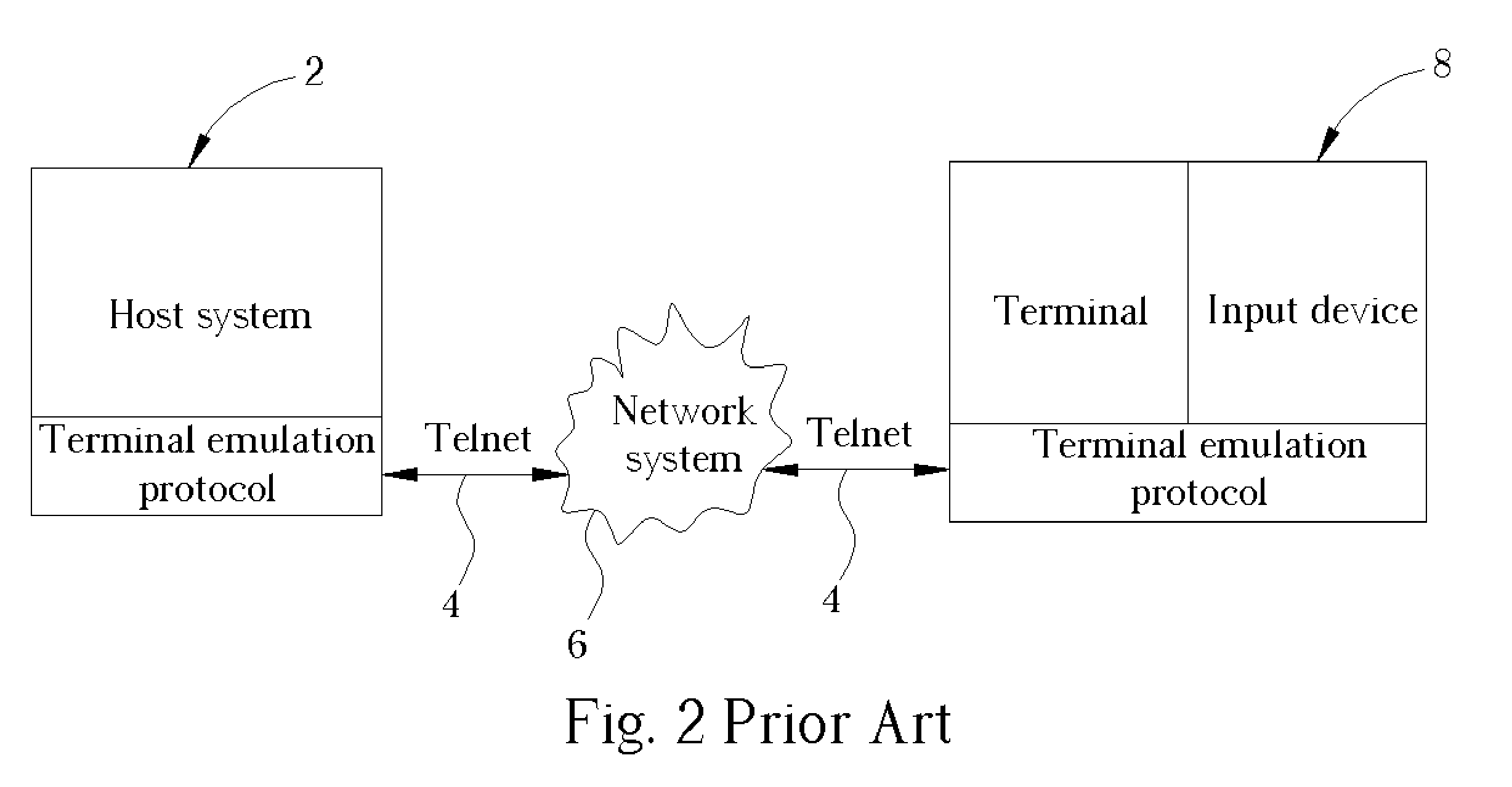
However there is problem of data transmission safety.
In addition, it is not convenient that the program corresponding with the foregoing terminal emulation protocol has to be installed on the host system 2 and the computer system 8, and that the compatibility of the program and operating systems also has to be considered.

Method used


Image

  • Remote terminal emulation system and method
  • Remote terminal emulation system and method
  • Remote terminal emulation system and method

Examples


Embodiment Construction

[0017] Please refer to FIG. 3. FIG. 3 is a functional block diagram of a remote terminal emulation system of a preferred embodiment according to the present invention. The remote terminal emulation system includes a host system 10 and a remote computer system 40. The remote terminal emulation system can present data outputted from the host system 10 on a terminal 44 of the remote computer system 40 quickly, that is, can process terminal emulation timely on the host system 10. The host system 10 includes an RS-232 interface 12 and an operating system compatible with a UNIX operating system. The remote computer system can be a personal computer and includes a WINDOWS operating system produced by Microsoft Corporation, an input device such as a keyboard, the terminal 44, and a network interface 49 corresponding with a TCP / IP communication protocol for electrically connecting to a network system 30.

[0018] The remote terminal emulation system further includes a terminal emulation unit 4...


PUM


Abstract

A remote terminal emulation system includes an information converting apparatus including a serial signal interface electrically connected to a remote computer system for transmitting data in serial signal form, a network interface electrically connected to a network system for transmitting network packets, and a converting unit for converting data between serial signal form and network packet form. The remote terminal emulation system further includes a terminal emulation unit for presenting the data in serial signal form on the terminal of the remote computer system according to a terminal emulation method so as to provide a remote-control function when the remote computer system receives the data in network packet form from a host system via the network system.

Description

BACKGROUND OF INVENTION [0001] 1. Field of the Invention [0002] The present invention relates to a remote terminal emulation system and more particularly, to a remote terminal emulation system for timely processing of remote terminal emulation to a host system via a network. [0003] 2. Description of the Prior Art [0004] Please refer to FIG. 1. FIG. 1 is a functional block diagram of a computer system 5 such as a personal computer connected to a host system 1 via an RS-232 interface and a cable 3 having a 25-pin or 9-pin connector according to the prior art. Users can use a terminal installed on the computer system 5, such as a screen and an input device such as a mouse or a keyboard, for inspecting or operating the host system 1. The display information of the host system 1 and the control data inputted from the input device by users can be converted into RS-232 serial signals and be transmitted between the host system 1 and the computer system 5. That is what's known as a serial te...

Claims


Application Information

Patent Timeline
Patent Type & Authority Applications(United States)
IPC IPC(8): G06F9/455G06F13/10
CPCG06F13/107
Inventor LIU, CHIN-SHUANG
Owner ICP ELECTRONICS
Learn More