
Transmitting apparatus and method, and receiving apparatus and method

a technology of receiving apparatus and transmitting apparatus, which is applied in the direction of selective content distribution, orthogonal multiplex, pulse technique, etc., can solve the problems of substantial performance degradation, floor in the bit error rate/signal-to-noise ratio relationship, etc., and achieve the effect of improving the encoding performance and simplifying the implementation and therefore the cost of the transmitter and receiver

Inactive Publication Date: 2009-07-02
SONY CORP
View PDF5 Cites 77 Cited by
  • Summary
  • Abstract
  • Description
  • Claims
  • Application Information

AI Technical Summary

Benefits of technology

[0008]An alternative decoding scheme that overcomes the bit error floors of classical Alamouti decoding has been disclosed in a presentation entitled “Alamouti in Varying Channels,” by Oliver Haffenden from BBC Research and published on 5 Oct. 2007 on the DVB standard server. This disclosure from Haffenden proposes a Zero Forcing technique to decode the Alamouti cells. However, according to a later disclosure, which is provided in a presentation by Oliver Haffenden entitled “Pilot Patterns for MISO / MIMO”, published on the DVB Server on 29 Nov. 2007, the grouping of the pairs of sub-carriers on which pairs of data symbols of Alamouti cells are transmitted within OFDM symbols, can restrict the location of the pilot sub-carrier symbols because of the requirement to transmit the data symbols of the Alamouti cell on pairs of neighbouring or adjacent sub-carriers of the OFDM symbol, although this pairing of sub-carriers cannot always be achieved causing some Alamouti pairs of cells to be split by pilot symbol sub-carriers. This proposal therefore causes a restriction on the pattern of the pilot symbol sub-carriers, and indeed this proposal includes a requirement to transmit pairs continuous pilot symbols on pairs of adjacent sub-carriers. Embodiments of the present invention utilise the alternative Haffended decoding scheme to provide a generalized technique for decoding that allows the transmission of modulation symbols which form Alamouti cells (pair wise encoded input symbols) so that the modulation symbols of the Alamouti cells do not have to be transmitted in neighbouring sub-carriers (space-frequency) or consecutive OFDM symbols (space-time). The advantages are twofold:
[0010]The two modulation symbols of an Alamouti cell can be spread over a frequency and / or time area (interleaving of Alamouti cell building blocks). The performance improvement due to the additional diversity dimension can be significant.
[0011]In some examples, the number of data bearing sub-carriers per OFDM symbol is even, so that the sub-carriers can be paired for transmitting the pairs of data symbols of the Alamouti cells. Furthermore, the modulator can be arranged in operation to position the data bearing sub-carrier symbols throughout each of the OFDM symbols with the effect that as far as possible the first and second modulation symbols and the third and fourth modulation symbols forming each of the Alamouti cells are located on adjacent pairs of sub-carriers. As such, if the Alamouti cells are transmitted on pairs of adjacent sub-carriers, then for these Alamouti cells, a simplified decoding technique according to the classical Alamouti decoding can be used, which assumes that a coefficient of the channel frequency response is the same for both data symbols of the Alamouti cell. For Alamouti cells which are not transmitted on adjacent pairs of sub-carriers, a more complicated technique can be used such as Zero Forcing, which assumes that a coefficient of the channel frequency response for each data symbol of the Alamouti cells is different. However, it has been discovered that when the OFDM symbols are received in environments with significant multi-path, the use of the classical Alamouti decoding, can cause substantial degradation in the performance, even when the pairs of data symbols of the cells are transmitted on adjacent sub-carriers. Therefore, in some examples an apparatus for receiving the OFDM symbols, which have been transmitted by a transmitting apparatus identified above, a data detector may be arranged to detect the pair of data symbols of the Alamouti cells carried by the sub-carriers using, for example a zero forcing or minimum mean square error technique, which uses a different estimate of a coefficient of the channel frequency response to recover an estimate of the pairs of the data symbols from the Alamouti cells for each of the data bearing sub-carriers within each of the first and second versions of the OFDM symbol regardless of the position of the data bearing sub-carriers.
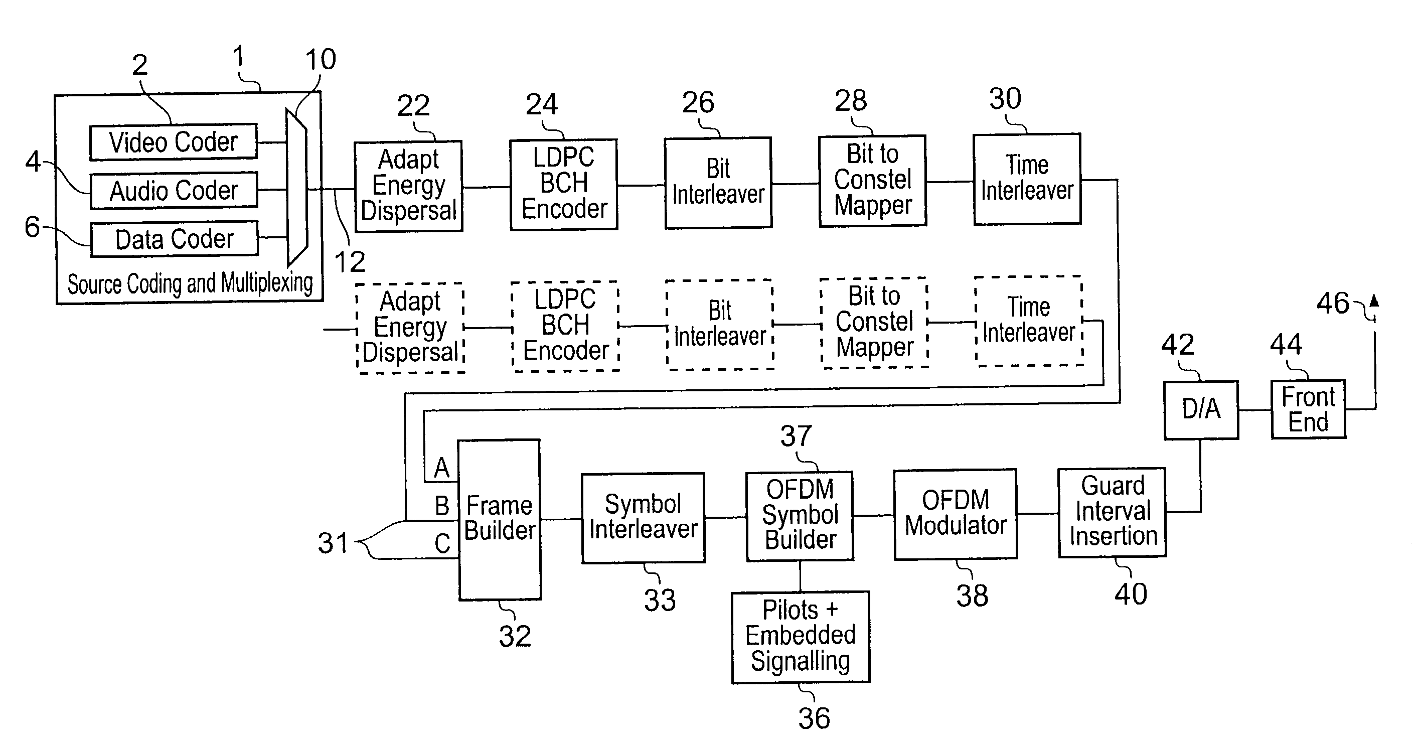
[0017]Thus, the apparatus for transmitting the data symbols can be operable in two modes a MISO mode in which Alamouti encoding is used and a SISO mode in which there is no Alamouti encoding, but the same pattern of pilot symbol sub-carriers can be used for both modes, thereby simplifying implementation and therefore cost of the transmitter and receiver. Thus in one example the scattered and continuous pilot symbol sub-carriers can be arranged in accordance with a Digital Video Broadcast standard such as DVB-T or DVB-T2.
[0018]As a further advantage, because the pairs of data symbols of the Alamouti cells can be arranged on the data bearing sub-carrier symbols of the OFDM symbol independently, the data symbols can be error correction encoded before being interleaved as pairs of Alamouti encoded symbol pairs thereby improving a performance of the encoding.

Problems solved by technology

This precondition can cause problems in pilot carrier locations and can result in a floor in the bit error rate / signal-to-noise ratio relationship, because an increase in the signal to noise ratio will not improve the bit error rate above a certain signal-to-noise value.
However, according to a later disclosure, which is provided in a presentation by Oliver Haffenden entitled “Pilot Patterns for MISO / MIMO”, published on the DVB Server on 29 Nov. 2007, the grouping of the pairs of sub-carriers on which pairs of data symbols of Alamouti cells are transmitted within OFDM symbols, can restrict the location of the pilot sub-carrier symbols because of the requirement to transmit the data symbols of the Alamouti cell on pairs of neighbouring or adjacent sub-carriers of the OFDM symbol, although this pairing of sub-carriers cannot always be achieved causing some Alamouti pairs of cells to be split by pilot symbol sub-carriers.
However, it has been discovered that when the OFDM symbols are received in environments with significant multi-path, the use of the classical Alamouti decoding, can cause substantial degradation in the performance, even when the pairs of data symbols of the cells are transmitted on adjacent sub-carriers.

Method used


Image

  • Transmitting apparatus and method, and receiving apparatus and method
  • Transmitting apparatus and method, and receiving apparatus and method
  • Transmitting apparatus and method, and receiving apparatus and method

Examples


example transmitter

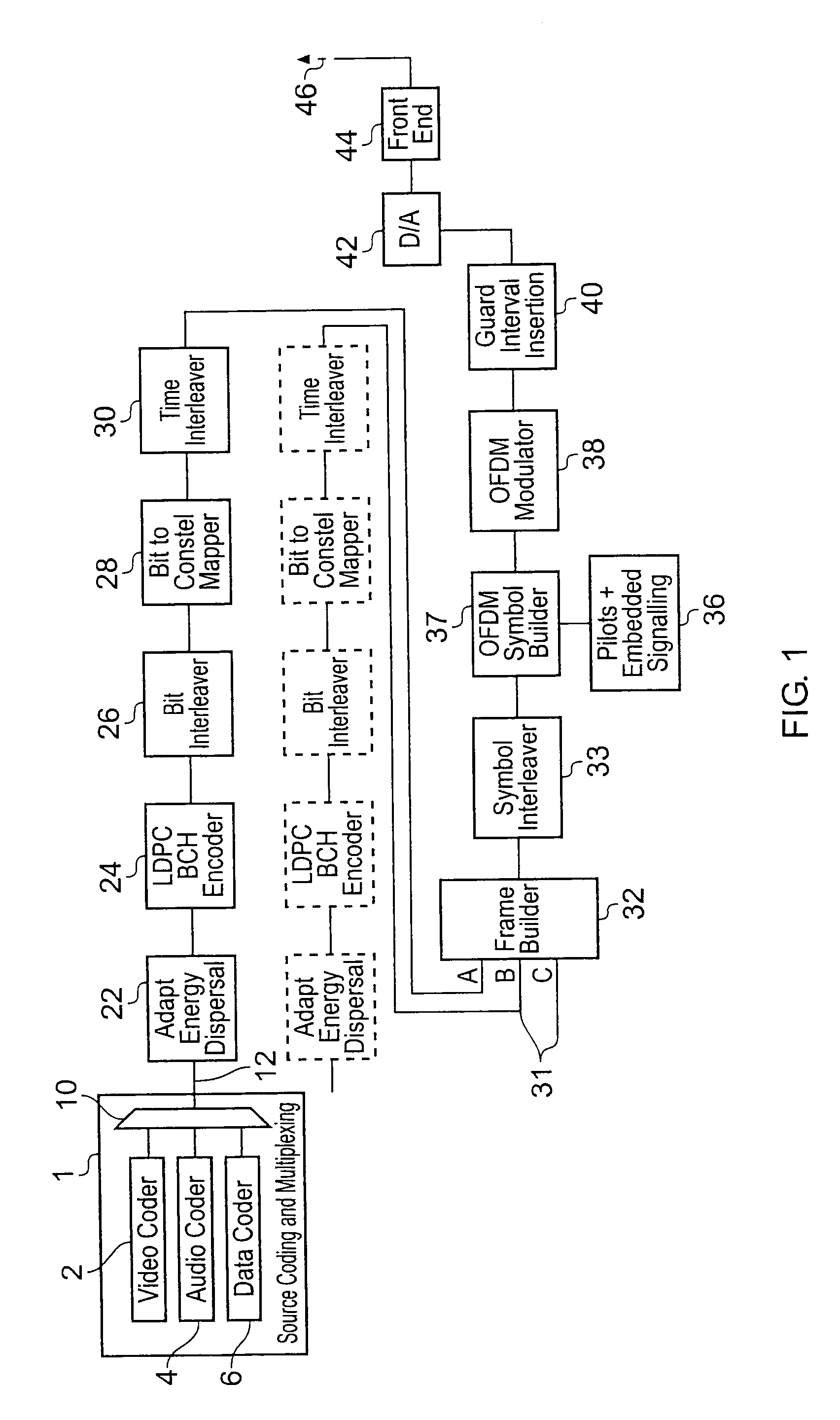
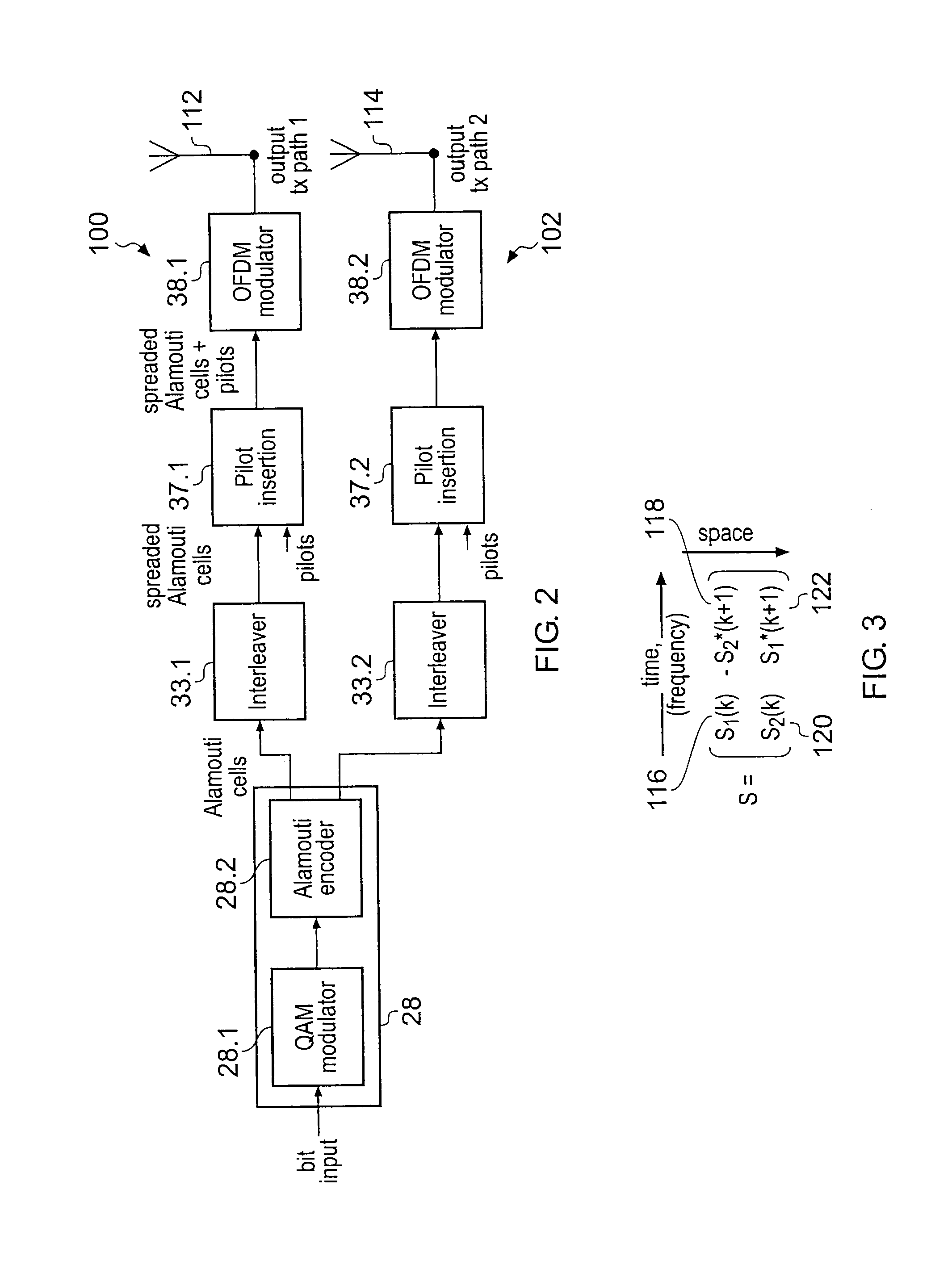
[0041]An example transmitter which utilises the present technique is shown in FIG. 2, which includes parts of the transmitter shown in FIG. 1, which are relevant to the explanation of the present technique. Thus some parts of the DVB-T2 transmitter shown in FIG. 1 have been omitted for clarity. In FIG. 2, the data to be transported is received by the bit to constellation mapper 28, which forms the data to be transported by an OFDM symbol or symbols into pairs of symbols.

[0042]As will be explained below, the data symbols are formed into pairs because the space time / frequency block codes used are Alamouti codes. As will be explained, the Alamouti encoding can be done either in space time or space frequency. As such the pairs of symbols formed within a QAM modulator 28.1 are either transported by the same OFDM symbol using different sub-carriers, or transported using two different OFDM symbols using the same sub-carrier in each symbol, one for each of the data symbols. As explained bel...


PUM


Abstract

A method of transmitting data symbols via an Orthogonal Frequency Division Multiplexed (OFDM) symbols, includes forming data symbols into pairs, generating a first pair of modulation symbols for each of the pairs of data symbols, the first pair of modulation symbols forming first and second modulation symbols of an Alamouti cell, forming a first version of the OFDM symbols by modulating the sub-carriers allocated for carrying the data with the first and second modulation symbols of the Alamouti cells, and modulating the one or more pilot carriers of the first version of the OFDM symbol according to a predetermined pattern. The method also comprises generating a second pair of modulation symbols for each of the pairs of data symbols, the second pair of modulation symbols forming third and fourth modulation symbols of the Alamouti cell formed for the pair of data symbols in the first version of the OFDM symbol, forming a second version of the OFDM symbol by modulating the sub-carriers allocated for carrying the data with the third and fourth modulation symbols of the Alamouti cell, modulating the one or more pilot carriers of the second version of the OFDM symbols according to the predetermined pattern, and transmitting the first version of the OFDM symbol via a first antenna, and the second version of the OFDM symbol via a second antenna. For at least one of the pairs of data symbols, the sub-carriers, on which each of the first and second modulation symbols and the third and fourth modulation symbols forming the Alamouti cells, are separated within the first and second versions of the OFDM symbol by at least one other data bearing sub-carrier or one or more of the pilot carriers.A transmitter and / or receiver according to the invention find application with the Digitial Video Broadcast-Terestrial 2 (DVB-T2) standard.

Description

FIELD OF INVENTION[0001]The present invention relates to transmitters for and methods of transmitting data via Orthogonal Frequency Division Multiplexed (OFDM) symbols, the OFDM symbols comprising a plurality of data bearing sub-carriers and one or more pilot carriers. The present inventions also relates to receivers and methods for receiving data from an OFDM symbol.BACKGROUND OF THE INVENTION[0002]The Digital Video Broadcasting-Terrestrial standard (DVB-T) utilises Orthogonal Frequency Division Multiplexing (OFDM) to communicate data representing video images and sound to receivers via a broadcast radio communications signal. There are known to be two modes for the DVB-T standard which are known as the 2k and the 8k mode. The 2k mode provides 2048 sub-carriers whereas the 8k mode provides 8192 sub-carriers. Similarly for the Digital Video Broadcasting-Handheld standard (DVB-H) a 4k mode has been provided, in which the number of data carriers is three thousand and twenty four.[0003...

Claims


Application Information

Patent Timeline
IPC IPC(8): H04L27/28
CPCH04L5/0044H04L5/0023H04L1/0071H04L1/0668H04N21/4382H04N21/2383H04L5/006H04L2001/0093H04L5/0048H04L1/0606H04H20/46H04H20/72H04L1/0643H04L25/0224H04L27/2627H04L27/2649H04L27/26134
Inventor STADELMEIER, LOTHARSCHILL, DIETMARSCHNEIDER, DANIEL
Owner SONY CORP
Learn More