Fabric and method of making the same

Active Publication Date: 2009-06-25
CCT LENDING LLC +1
View PDF16 Cites 28 Cited by
  • Summary
  • Abstract
  • Description
  • Claims
  • Application Information

AI Technical Summary

Benefits of technology

[0010]It is an object of the present invention to provide a convenient, easy-to-use, flexible fabric that remains cool for an extended period of time when contacted against an object to be cooled, such as a person's skin or an inanimate object for which temperature maintenance is desirable, and a method of making the fabric. It is also an object of the present invention to provide a moisture management fabric that can assist in maintaining a sustained thermal condition of an object for an extended period of time with minimal effort and no temperature-regulating chemicals in the fabric. Further, it is an object of the present invention to provide a method of manufacturing such a fabric with such characteristics.
[0014]Present manufacturing processes that include a peaching step perform the peaching on the front side only, or at least do so first, thereby minimizing the ability to pull fibers on the front side toward the back side of the fabric. Instead, the peaching on the front side is done to create texture, pile and / or “hand” on the front side of the fabric, such as to enhance the insulative characteristics of the fabric with little or no regard for the condition of the back side or establishing a cooling functionality.
[0015]The peaching step of the manufacturing method of the present invention involves peaching both the front and back sides of the fabric multiple times each to create a homogeneous blend of the different materials. That is, at least portions of the fiber material of the front side and the fiber material of the back side become entangled with one another. These homogeneous blends of materials having dissimilar characteristics maintain an atmosphere that is conducive to maximizing the uniqueness of the individual fiber properties and thus control / regulate the rate of evaporation.
[0016]The fabric of the present invention is configured to facilitate liquid removal from the surface of the object, store liquid therein, and slow the evaporation of liquid away from the fabric to the atmosphere. Any type of prior commercially available fabric designed to cool is limited to causing rapid transport of liquid away from the skin and equally rapid transport of that liquid completely out of the fabric. In other words, prior cooling fabrics using no chemicals to induce cooling artificially, are configured to get liquid away from the skin as soon as possible and nothing more. This may achieve short term cooling, but fails to enable longer term cooling, particularly for individuals who are not exercising (and thereby generating their own moisture to produce evaporative cooling). The fabric of the present invention utilizes the cooling effect available from retained liquid. By withdrawing that liquid, at what is likely to be its highest temperature at the surface of the object, from the surface, storing the liquid within the fabric so that it cools down to become a more effective evaporative agent than it was when at a higher temperature, and restricting the ability of that cooled liquid to quickly evaporate from the atmosphere-side of the fabric, ensures a substantially longer cooling capability than has been made available.
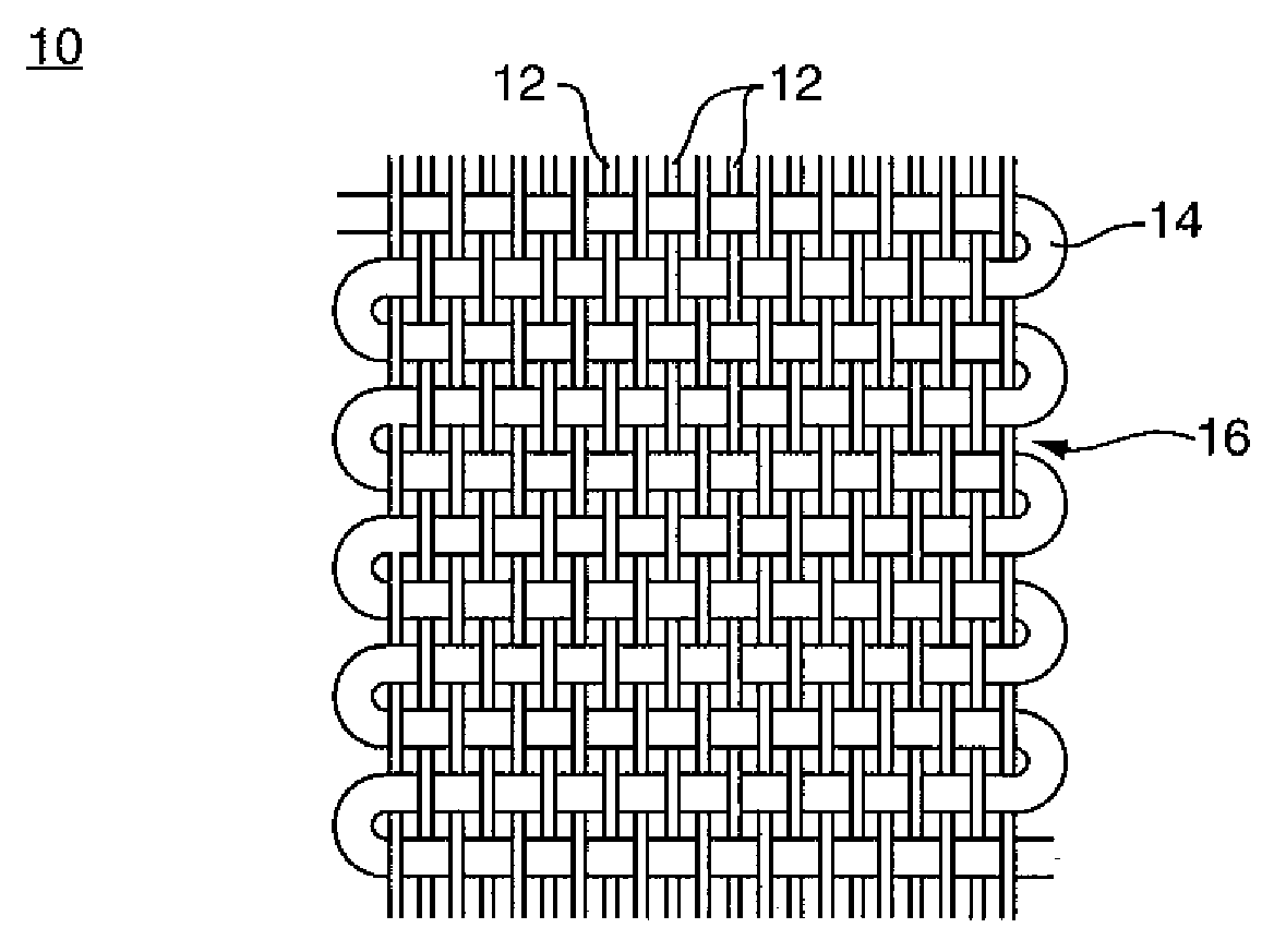
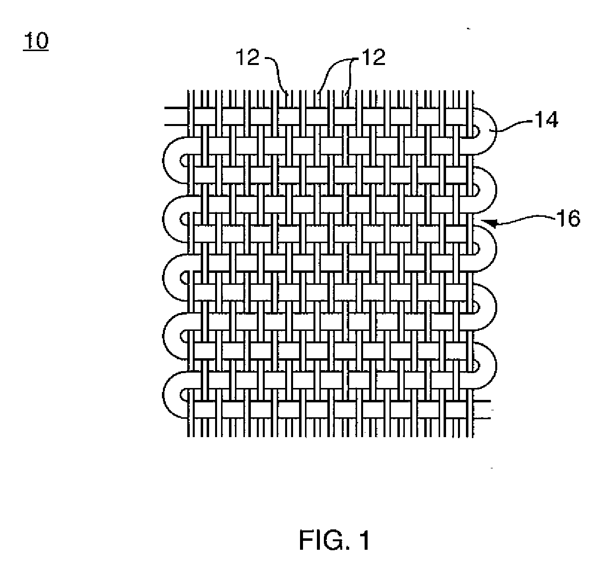
[0017]The present invention is directed to creating in a fabric a controlled environment that maximizes wicking where desired and retention of liquid molecules within the fabric structure. The invention utilizes yarns / fibers organized in the manner described herein to maximize fabric traits that interfere with the normal process of evaporation away from the fabric. These traits include diverting liquid from the surfaces of individual fibers near the object to the interior of the fabric, trapping the liquid at the interior, and, ultimately, slowing the rate of evaporation from the fabric. As used herein, “evaporation” means the change of a liquid into a vapor at a temperature below the boiling point of that liquid; a condition that exists at the surface of the liquid, where molecules with the highest kinetic energy are able to escape, when this happens, the average kinetic energy of the liquid is lowered, and its temperature decreases. With that in mind, the present invention is configured to facilitate evaporation within the fabric as much as possible to aid in the cooling of the object while also slowing evaporation of liquid from the fabric itself. 
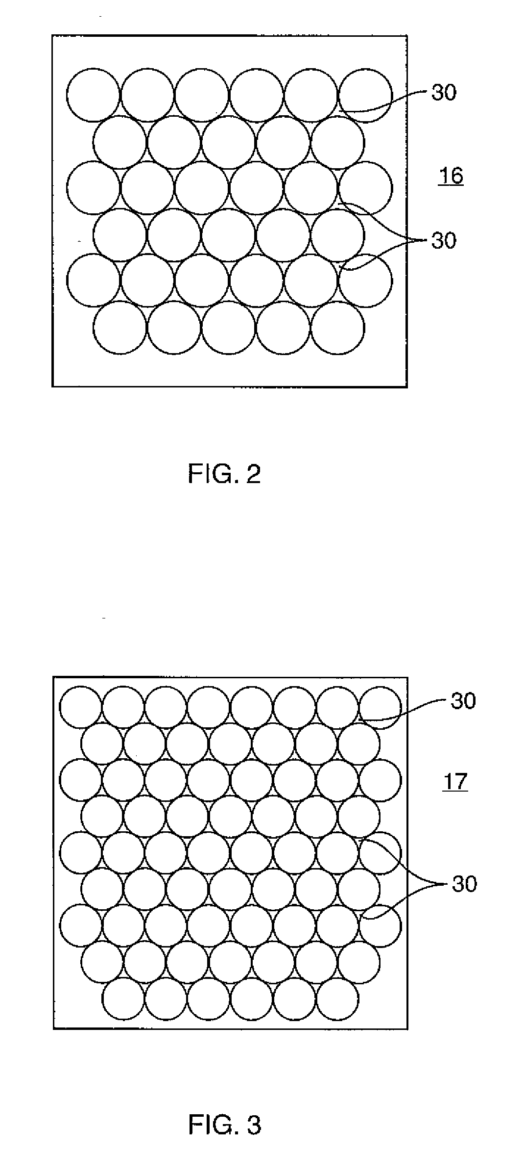
Fiber characteristics, density and arrangement all have a hand in regulating evaporation rate. The present invention involves fiber selection, positioning and physical modification to achieved desired evaporation control. For example, the intermediary portion of the fabric includes a network of interstices or capillaries the configuration of which is defined by the fiber shape and the arrangement of fibers with respect to one another. That network slows the progression of liquid completely out of the fabric and allows for evaporative cooling of the liquid that facilitates heat transfer from the object to be cooled.
[0019]The cooling properties of the fabric of the present invention, which may include maintaining an object at a selected temperature for a period of time, makes it amenable to being used in a large variety of applications. For example, the fabric may be used to wholly or partially form a plurality of apparel and personal products that can be worn or otherwise used by a person in the hot sun or while exercising to keep cool. As another example, the fabric may be used to wholly or partially form a plurality of skin-associated medical health products that can be used to keep a patient cool. The fabric of the present invention satisfies this need because it becomes cool at its interface with the patient's skin by wicking away any “warm” liquid (e.g., perspiration), storing that liquid in the intermediary portion such that it begins to cool by slowing its progression through to the other surface of the fabric and enabling the retained relatively cooler liquid to provide further cooling of the skin. The fabric may also be used to keep inanimate objects cooled, such as materials to be transported, for example. The fabric created through the combination of materials and manufacturing steps described provides maximum wicking and absorption where needed near the object, and moisture storage characteristics that allow for evaporative cooling within the fabric and reducing the rate of normal liquid evaporation away from the fabric.

Problems solved by technology

These solutions, however, are impractical to those who must remain outside, such as a highway worker, for example, and are unsatisfying to those who wish to remain outside, such as an athlete, a theme park patron or beachgoer, for example.
These efforts are largely ineffective and are not completely satisfying.
While this technique is effective, it is effective only for a very short period of time, perhaps one minute or so.
The downfall of this technique is that the individual's body heat and the ambient temperature rapidly warm the initially cold water to the point that the water is no longer cooling against the skin.
The most commonly employed “solution” to this problem, which is to repeatedly saturate the towel or facecloth in cold water as needed, is not satisfying because it requires much effort, and is not practical because it requires the individual to constantly be near a cold water source.
The availability of ice in any given situation may be limited.
Its formation can be costly and its ability to conform to most any area of the body is severely limited.
However, the alcohol is drying to the skin and can lead to rashes and other skin irritations.
The chemicals employed for that purpose can be hazardous and ineffective if their carriers are breached.
Presently, there is no effective non-chemical means of thermal regulating the rate of evaporation in a device that can be used to conform with a person's body, such as around the neck, for example.

Method used


Image

  • Fabric and method of making the same
  • Fabric and method of making the same
  • Fabric and method of making the same

Examples


example

[0061]Fabric formation. A fabric of the invention having about 77% polyester and about 23% nylon was made in this Example. The warp yarn included as part of the fabric was DTY and SDH and had a relative thickness of about 75 deniers. The weft yarn included as part of the fabric was DTY and had a relative thickness of about 160 deniers per 144 fibers.

[0062]Prior to being woven, the yarns were added to an air jet weaving loom (having a width of 10,612 ends) at a density of a thread count of about 160 threads her square inch. The yarns were then woven to form the fabric according to standard protocols that are well known to those of ordinary skill in the art.

[0063]Printing pre-treatment. After being woven, the fabric was scoured by using Zelcon to remove any dirt, wax, oil, or other contaminants that may have been present.

[0064]Fabric Printing. After scouring, a plurality of multi-colored designs was printed onto the face of the fabric by using a sublimation printer according to protoc...


PUM

PropertyMeasurementUnit
Hydrophilicityaaaaaaaaaa
Transport propertiesaaaaaaaaaa

Abstract

A fabric for thermal management including the cooling of an object, such as a person's skin. The fabric is formed of a plurality of materials including at least one liquid transport enhancing material and at least one evaporative transport impeding material. When the fabric is in use, the transport enhancing material is located near an object to be cooled, while the evaporation impeding material is spaced away from the object. The fabric is peached so that there is an entanglement of the two materials. Peaching is performed on both sides of the fabric, but initially on the side with the transport enhancing material such that a portion of the evaporation impeding material is pulled into the fabric core. A method of making the fabric is also described.

Description

CROSS REFERENCE TO RELATED APPLICATION[0001]This application claims the priority benefit of U.S. provisional patent application Ser. No. 61 / 014,973, filed Dec. 19, 2007, entitled FABRIC AND METHOD OF MAKING THE SAME of the same named inventors. The entire content of the priority application is incorporated herein by reference.BACKGROUND OF THE INVENTION[0002]1. Field of the Invention[0003]The present invention relates to a fabric and a method of making the fabric. More specifically, the present invention relates to a fabric that is made to regulate moisture dispersal therethrough to enhance its ability to provide evaporative cooling. Even more specifically, the present invention relates to a fabric that becomes cool when activated by liquid and remains cool for an extended period of time thereafter, and a method of making the same fabric.[0004]2. Description of the Prior Art[0005]Although everyone enjoys a warm sunny day, there are times when the outside temperature is too hot to be...

Claims


Application Information

Patent Timeline
IPC IPC(8): D03D25/00B05D3/00D03D15/00
CPCD03D15/00D04B9/00D03D15/0077D03D15/0083D03D15/0094D10B2101/20D10B2331/02D10B2331/04D10B2401/021D10B2401/022D10B2401/14D10B2403/0114D10B2501/00D10B2509/026F28C3/08D03D1/00D03D15/0066Y10T442/30Y10T428/249921Y10T442/40D03D15/258D03D15/49D03D15/43D03D15/37D03D15/50D03D15/527D03D15/283A41D13/0056
Inventor ACKROYD, DENNIS D.LAI, FRANCIS
Owner CCT LENDING LLC
Why Eureka
Try Eureka