Plate Heat Exchanger, Method for Its Production, and Its Use
- Summary
- Abstract
- Description
- Claims
- Application Information
AI Technical Summary
Benefits of technology
Problems solved by technology
Method used
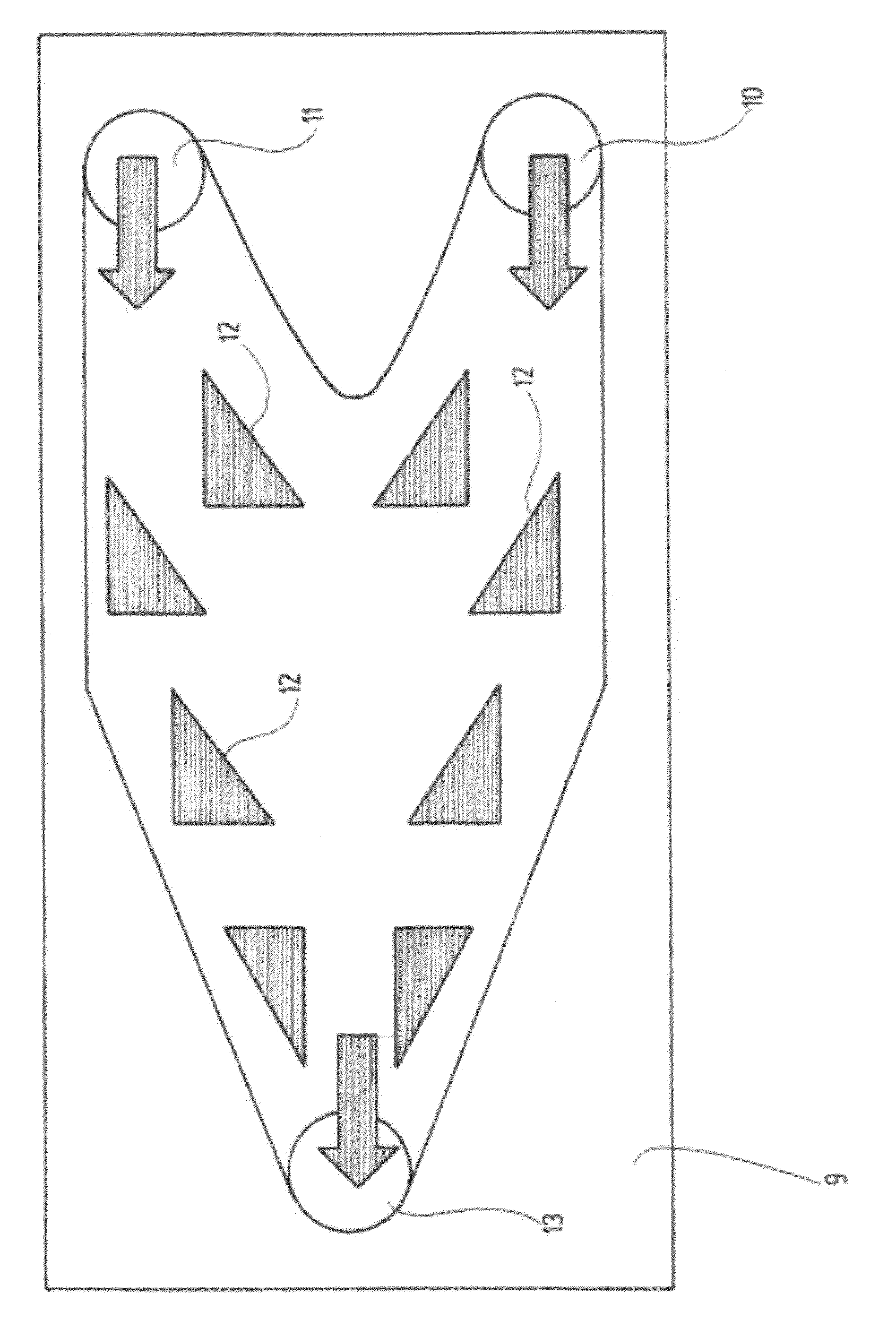
Image

Examples
examples
[0050]The following example serves for further explanation of the invention.
Example of Application of a Heat Exchanger
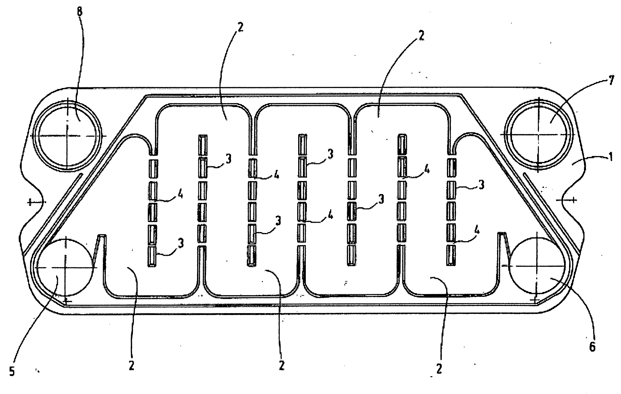
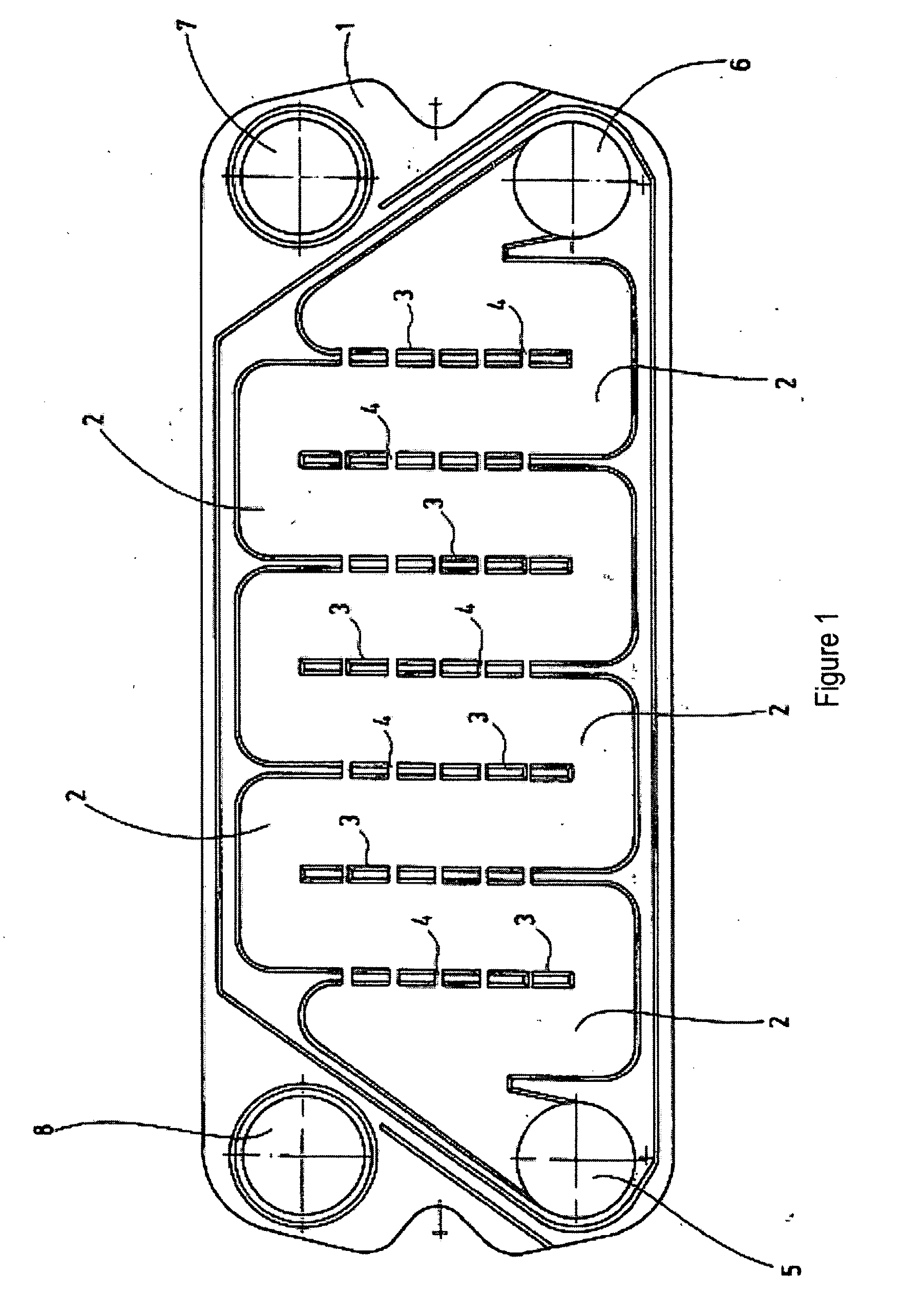
[0051]A ceramic exchanger is produced with heat exchanger plates in the manner of FIG. 1. The plates have a length of 500 mm, a base thickness of 3 mm and guide channels with a height of 3.5 mm. The side walls have apertures of a width of 3 mm. Four heat exchanger plates and one cover plate are used for the production of the heat exchanger block, all the components consisting of sintered silicon carbide with bimodal grain size distribution. All the ceramic plates are stacked and integrally and seamlessly joined to form a monolithic block. The plates are arranged in the block in such a way that two substance flows can exchange heat in counterflow. The hermetically sealed heat exchange block made from sintered silicon carbide is provided with four metallic flanges with an inside diameter of 50 mm. The heat exchanger apparatus is operated with aqueous media. With a thro...
PUM
 Abstract
Description
Claims
Application Information
 - R&D
- Intellectual Property
- Life Sciences
- Materials
- Tech Scout
- Unparalleled Data Quality
- Higher Quality Content
- 60% Fewer Hallucinations
Browse by: Latest US Patents, China's latest patents, Technical Efficacy Thesaurus, Application Domain, Technology Topic, Popular Technical Reports.
© 2025 PatSnap. All rights reserved.Legal|Privacy policy|Modern Slavery Act Transparency Statement|Sitemap|About US| Contact US: help@patsnap.com