Clutch control system for vehicle

Active Publication Date: 2009-06-04
HONDA MOTOR CO LTD
View PDF4 Cites 22 Cited by
  • Summary
  • Abstract
  • Description
  • Claims
  • Application Information

AI Technical Summary

Benefits of technology

[0007]It is an object of an embodiment of the present invention, in connection with a clutch control system for a vehicle having a hydraulic type clutch in the course of a power transmission path between an engine and a drive wheel, to enhance the operation response of the clutch and to suppress the influence of a hysteresis present in the oil pressure-stroke characteristic.
[0012]According to an embodiment of the present invention, the control oil pressure is kept at a predetermined stand-by oil pressure when the clutch is disconnected, whereby it is made possible to cancel the chattering and an operating reaction force of the clutch and to exert a pre-load onto the oil pressure line (to compensate the allowance pressure), thereby enhancing the operation response at the time of clutch connection.
[0013]In addition, at the time of bringing the clutch from the connected state into the disconnected state, the control oil pressure is lowered to an oil pressure being below the stand-by oil pressure and being near 0 (near the atmospheric pressure) and is thereafter increased again to the stand-by oil pressure, whereby the clutch can be completely disconnected while obviating the influence of a hysteresis present in oil pressure-stroke characteristic, and the clutch can be prevented from being dragged under the influence of the hysteresis.
[0014]According to an embodiment of the present invention, dragging of the clutch can be securely prevented from occurring when the vehicle is stopped.
[0015]According to an embodiment of the present invention, the operation response at the time when the clutch is connected can be enhanced efficiently.
[0016]According to an embodiment of the present invention, in a twin clutch needing stand-by in a disconnected state before connection of the clutch, it is possible to suppress the operational delay at the time of shifting from one clutch to the other and to prevent the clutch from being dragged at the time of stand-by.

Problems solved by technology

In this case, even if the clutch control oil pressure is simply lowered from the clutch connected condition to the stand-by oil pressure, the clutch may not be completely disconnected but may be dragged under the influence of a hysteresis present in the oil pressure-stroke characteristic.

Method used


Image

  • Clutch control system for vehicle
  • Clutch control system for vehicle
  • Clutch control system for vehicle

Examples


Embodiment Construction

[0025]Now, an embodiment of the present invention will be described below referring to the drawings. The front, rear, left, right sides and the like in the following description are the same as those with respect to the vehicle unless otherwise specified. In the figures, arrow FR indicates the forward direction (front side) with respect to the vehicle, arrow LH indicates the leftward direction (left side) with respect to the vehicle, and arrow UP indicates the upward direction (upper side) with respect to the vehicle.

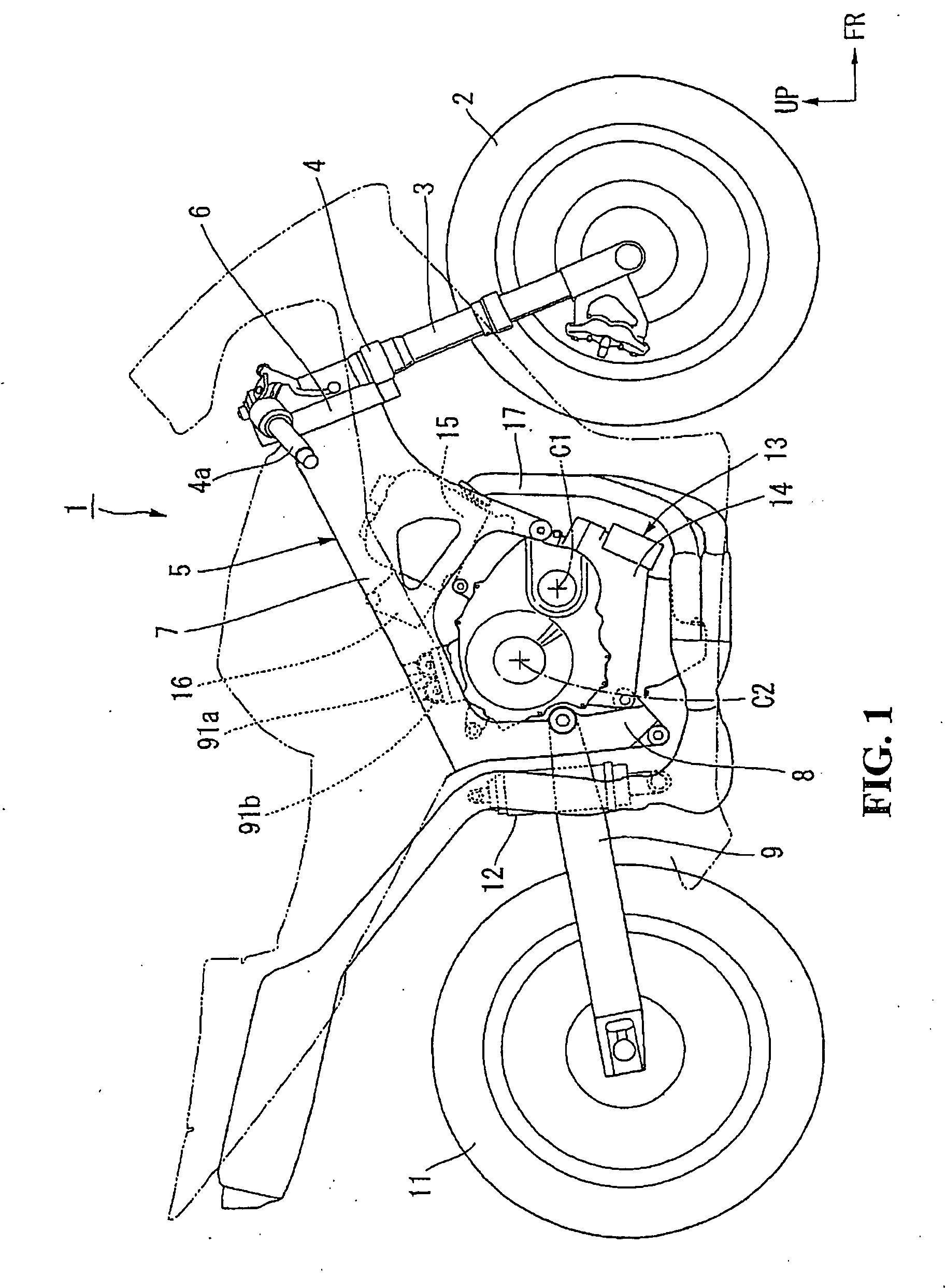
[0026]As shown in FIG. 1, an upper part of a front fork 3 rotatably supporting a front wheel 2 of a motorcycle (saddle ride type vehicle) 1 is steeringly rotatably supported on a head pipe 6 at a front end part of a body frame 5 through a steering stem 4. A steering handle 4a is attached to an upper part of the steering stem 4 (or the front fork 3). From the head pipe 6, a main frame 7 extends rearwards to be connected to a pivot plate 8. Front end parts of swing arms 9...


PUM


Abstract

In a clutch control system for a vehicle having a hydraulic type clutch in the course of power transmission between an engine and a drive wheel the operational response of the clutch is enhanced and the influence of a hysteresis present in oil pressure-stroke characteristic is suppressed. When the clutch is disconnected, a control oil pressure thereof is maintained at a predetermined stand-by oil pressure (allowance compensating oil pressure) P1. At the time of connecting the clutch, the control oil pressure is increased to a predetermined connection oil pressure P2. In bringing the clutch from the connected state into the disconnected state, the control oil pressure is lowered to an oil pressure P3 being below the stand-by oil pressure P1 and being near 0, and is thereafter increased again to the stand-by oil pressure P1.

Description

CROSS-REFERENCE TO RELATED APPLICATIONS[0001]The present application claims priority under 35 USC 119 to Japanese Patent Application No. 2007-310927 filed on Nov. 30, 2007 the entire contents of which are hereby incorporated by reference.BACKGROUND OF THE INVENTION[0002]1. Field of the Invention[0003]The present invention relates to a clutch control system for a vehicle.[0004]2. Description of Background Art[0005]A clutch control system for a vehicle is known wherein a hydraulic type clutch is put into a connected state by a supply of oil pressure which is supplied externally. A clutch control system is known wherein oil pressure is varied stepwise through different characteristics until a desired clutch control oil pressure is reached. See, for example, Japanese Patent Laid-open No. 2003-56687.[0006]In the case of a hydraulic type clutch which is put into a connected state by a supply of oil pressure which supplied externally, a stand-by oil pressure corresponding to an allowance p...

Claims


Application Information

Patent Timeline
IPC IPC(8): F16D48/06G06F17/00F16D25/00
CPCF16D21/06F16D48/0206F16D2500/70412F16D2021/0661F16D2500/70406F16D48/066F16D2021/0692F16D25/10F16D25/0638
Inventor FUKAYA, KAZUYUKITSUKADA, YOSHIAKIOZEKI, TAKASHIKOJIMA, HIROYUKINEDACHI, YOSHITAKI
Owner HONDA MOTOR CO LTD
Why Eureka
Try Eureka