Feedthrough capacitor mounted structure
- Summary
- Abstract
- Description
- Claims
- Application Information
AI Technical Summary
Benefits of technology
Problems solved by technology
Method used
Image
Examples
first embodiment
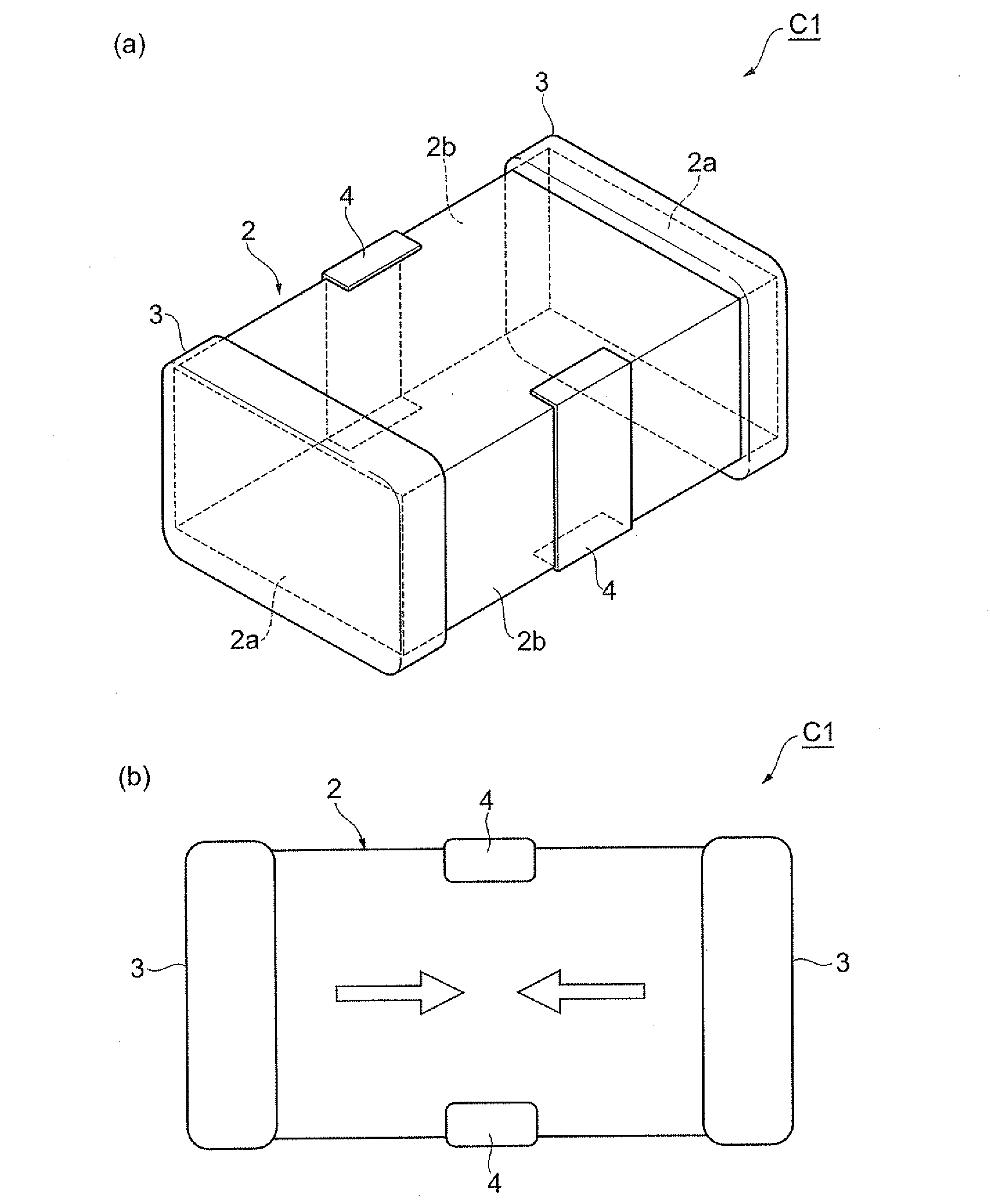
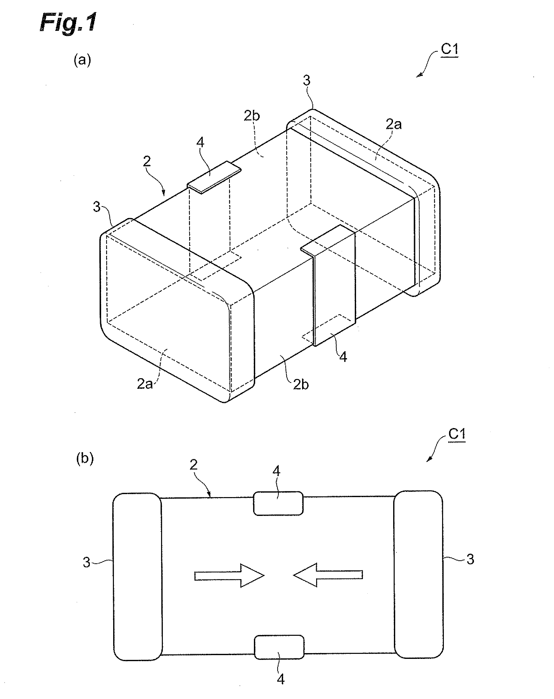
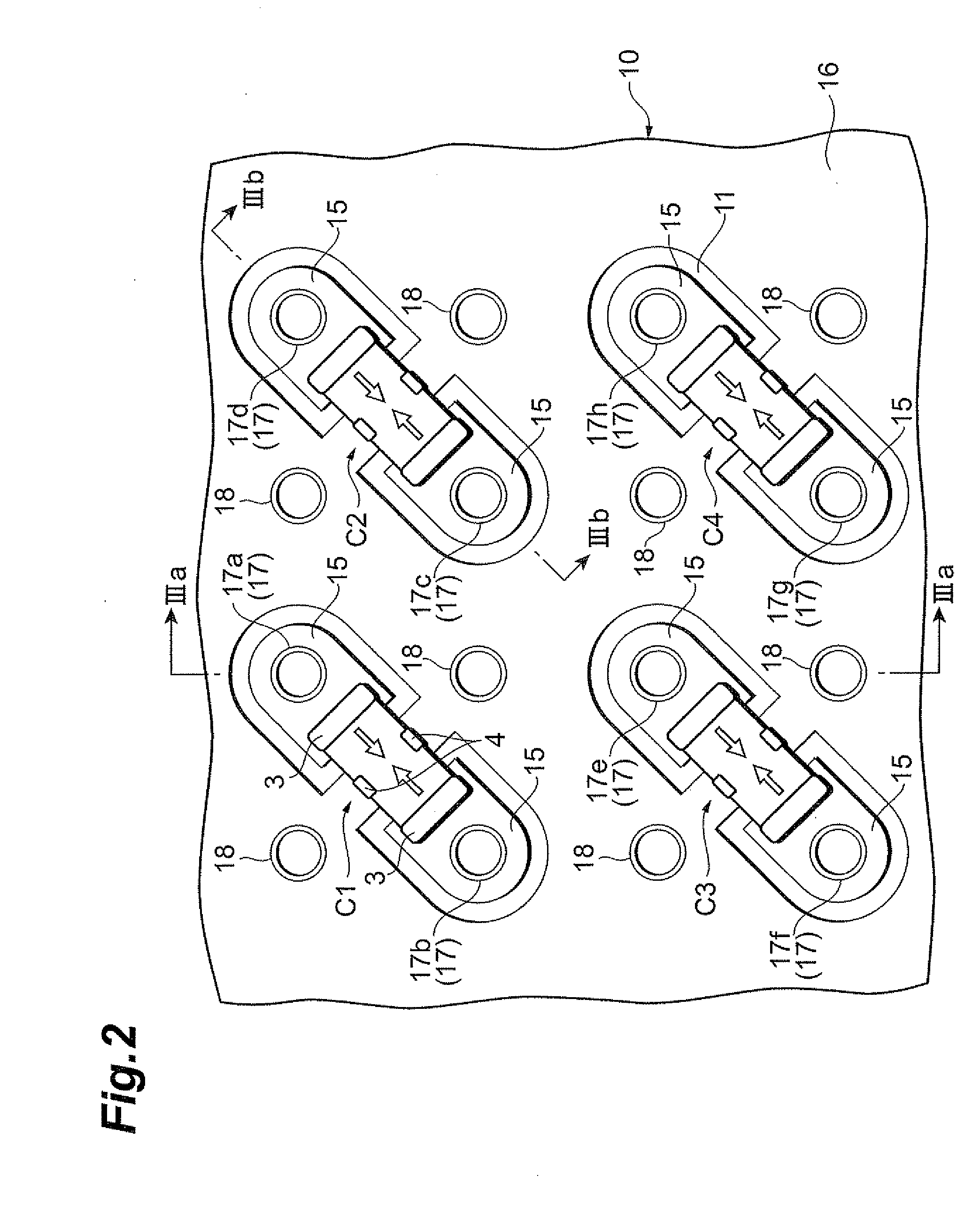
[0025]FIG. 1(a) is a perspective view of a feedthrough capacitor and FIG. 1(b) a top plan view of the feedthrough capacitor. FIG. 2 is a top plan view showing a feedthrough capacitor mounted structure according to the first embodiment. FIG. 3(a) is a sectional view along line IIIa-IIIa in FIG. 2 and FIG. 3(b) a sectional view along line IIIb-IIIb in FIG. 2. FIG. 2 is depicted without illustration of soldered portions between feedthrough capacitors and a substrate, for better viewing of the drawing.
[0026]The feedthrough capacitor mounted structure with feedthrough capacitors on the substrate according to the first embodiment will be described below with reference to FIGS. 1 to 3.
[0027]The feedthrough capacitor C1 is a so-called 3-terminal feedthrough capacitor. The feedthrough capacitor C1, as shown in FIG. 1(a), is constructed with a capacitor element body 2 of a nearly rectangular parallelepiped shape, a pair of terminal electrodes 3, and a pair of ground electrodes 4.
[0028]The ter...
second embodiment
[0042]The second embodiment will be described below based on FIG. 4. FIG. 4 is a top plan view showing a feedthrough capacitor mounted structure with feedthrough capacitors on a substrate according to the second embodiment. The feedthrough capacitors are soldered to the substrate in practice, but FIG. 4 is depicted without illustration of soldered portions between the feedthrough capacitors and the substrate, for better viewing of the drawing.
[0043]In the second embodiment, feedthrough capacitors C11, C12 are mounted on the mounting surface of the substrate 10. The feedthrough capacitors C11, C12 each have the same configuration as the feedthrough capacitor C1 in the first embodiment.
[0044]The feedthrough capacitor C11 is laid between a pair of power-side via holes 17 adjacent to each other in a direction intersecting with the row direction and also adjacent to each other in a direction intersecting with the column direction. The feedthrough capacitor C12 is laid between a pair of p...
third embodiment
[0051]The third embodiment will be described below based on FIG. 5. FIG. 5 is a top plan view showing a feedthrough capacitor mounted structure with feedthrough capacitors on a substrate according to the third embodiment. The feedthrough capacitors are soldered to the substrate in practice, but FIG. 5 is depicted without illustration of soldered portions between the feedthrough capacitors and the substrate, for better viewing of the drawing.
[0052]In the third embodiment, feedthrough capacitors C21-C24 are mounted on the mounting surface of the substrate 10. The feedthrough capacitors C21-C24 each have the same configuration as the feedthrough capacitor C1 in the first embodiment.
[0053]The feedthrough capacitor C21 is laid between a pair of power-side via holes 17a, 17b adjacent in an oblique direction. The terminal electrodes 3, 3 of the feedthrough capacitor C21 are connected to the respective power-side land electrodes 15 corresponding to the power-side via holes 17a, 17b.
[0054]T...
PUM
 Abstract
Description
Claims
Application Information
 - R&D
- Intellectual Property
- Life Sciences
- Materials
- Tech Scout
- Unparalleled Data Quality
- Higher Quality Content
- 60% Fewer Hallucinations
Browse by: Latest US Patents, China's latest patents, Technical Efficacy Thesaurus, Application Domain, Technology Topic, Popular Technical Reports.
© 2025 PatSnap. All rights reserved.Legal|Privacy policy|Modern Slavery Act Transparency Statement|Sitemap|About US| Contact US: help@patsnap.com


