
Inkjet printing head and inkjet printing apparatus

a printing head and inkjet technology, applied in printing, inking apparatus, other printing apparatus, etc., can solve the problems of poor heat transfer efficiency between the printing head and the heat pipe, the printing element substrate cannot be provided in the close vicinity of the heat pipe, and the printing head's temperature rise during printing operation, etc., to achieve high printing reliability and higher density

Inactive Publication Date: 2009-06-04
CANON KK
View PDF8 Cites 18 Cited by
  • Summary
  • Abstract
  • Description
  • Claims
  • Application Information

AI Technical Summary

Benefits of technology

[0009]In view of the disadvantages of the conventional technique as described above, it is an objective of the present invention to provide an inkjet printing head that has a high printing reliability even when a printing head having a long length and a higher density is used to perform a high-speed printing operation.
[0016]The present invention can suppress the temperature rise of the inkjet printing head and an uneven temperature distribution in the inkjet printing head due to a printing operation with a higher speed and an arrangement of ejection openings with a higher density to prevent the fluctuation in the ejection amount and an ejection failure due to a temperature rise. At the same time, a higher speed and a higher image quality can be both established and the reliability during a continuous printing operation can be remarkably improved.

Problems solved by technology

The printing head having a longer length and a higher speed as described above causes an increased energy inputted to the printing head to consequently cause an increased temperature rise of the printing head during a printing operation.
Thus, a disadvantage has been caused where a printing element substrate as a heat source cannot be provided in the close vicinity of the heat pipe.
The externally-attached heat pipe also causes a limited area at which the heat pipe contacts with the printing head, thus causing a poor heat transfer efficiency between the printing head and the heat pipe.
However, the conventional configuration is disadvantageous when the printing head having a longer length and a higher density is used to continuously perform a printing operation for a longer time.
This is due to that the conventional configuration cannot provide a heat transfer efficiency enough to suppress a defective printing due to an uneven temperature distribution and a temperature rise in the printing head due to the long-time printing.

Method used


Image

  • Inkjet printing head and inkjet printing apparatus
  • Inkjet printing head and inkjet printing apparatus
  • Inkjet printing head and inkjet printing apparatus

Examples


first embodiment

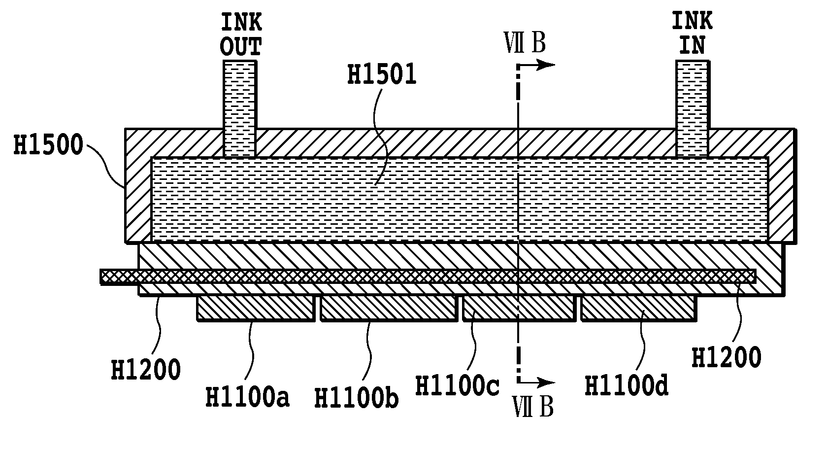
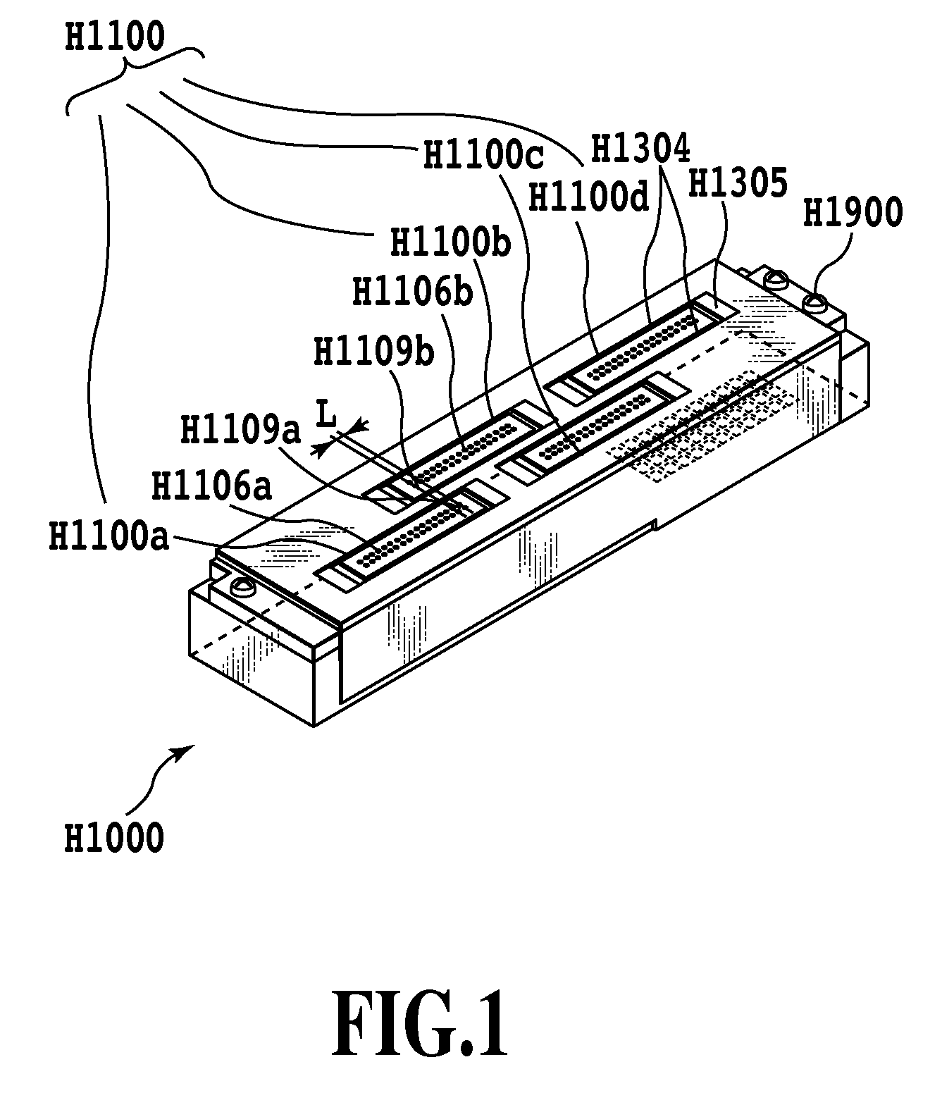
[0061]FIG. 7A illustrates a longitudinal cross section of the inkjet printing head according to the first embodiment of the present invention. FIG. 7B is a lateral cross-sectional view taken along VIIB-VIIB. The support plate H1200 has thereon the four printing element substrates H1100a, H1100b, H1100c, and H1100d arranged in a staggered pattern.

[0062]FIG. 8 is a schematic view illustrating only the support plate H1200 of FIG. 7B. The support plate H1200 is a one substrate composed of two plate-like members that are adhered to each other by adhesive agent. At the opposite side of a face of the first support plate H1200-1 on which the printing element substrate is provided, three grooves are formed independently. By adhering the second support plate H1200-2 to the first support plate H1200-1, the respective grooves are covered to provide a passage H2001, as a storage space in which the heat pipe H2000 is provided. The passage H2001 in which the heat pipe is provided has a cross secti...

second embodiment

[0067]FIG. 9A is a longitudinal cross section of the inkjet printing head according to the second embodiment of the present invention. FIG. 9B is a lateral cross-sectional view taken along IXB-IXB of FIG. 9A. In this embodiment, the support plate H1200 includes therein the heat pipe H2000 and a cooling medium flow path H2002-2. In this embodiment, the heat pipe H2000 is provided at the printing element substrate H1100 in the support plate H1200 and the heat pipe H2000 and the flow path H2002-2 are arranged in the thickness direction of the support plate H1200. In other words, the printing element substrate H1100, the passage, as a storage space in which is the heat pipe H2000 is provided, and the flow path H2002-2 are provided in the listed order in the thickness direction of the support plate.

[0068]FIG. 10 is a schematic view illustrating only the support plate H1200 of FIG. 9B. The support plate H1200 is composed of three members that are mutually adhered by adhesive agent to conf...

third embodiment

[0078]FIG. 11 is a schematic view illustrating the support plate H1200 in the inkjet printing head according to the third embodiment of the present invention. The third embodiment is different from the second embodiment in that the alumina support plate H1200 of the inkjet printing head is changed to a layered structure obtained by layering and burning green sheets. This configuration eliminates the need to adhere the support plate H1200 by adhesive agent having a poor thermal conductivity. Thus, the substrate can be made only of alumina having a high thermal conductivity. Thus, when compared with the second embodiment, the third embodiment can suppress the temperature rise of the printing head.


PUM


Abstract

A temperature rise of a head due to a printing operation with a higher speed and a higher density is suppressed. To realize this, an inkjet printing head is provided in which a plurality of printing element substrates having an ejection opening array consisting of a plurality of ejection openings for ejecting ink are arranged on a support plate in a direction of the ejection opening array. The support plate includes therein a heat pipe and a flow path through which cooling liquid is flowed.

Description

BACKGROUND OF THE INVENTION[0001]1. Field of the Invention[0002]The present invention relates to an inkjet printing apparatus that ejects ink to perform a printing operation and an inkjet printing head used for the printing apparatus.[0003]2. Description of the Related Art[0004]Conventionally, the inkjet printing apparatus achieves a reduced running cost for color images and also can have a smaller size. Thus, the inkjet printing apparatus has been widely used for computer-related output devices and are commercialized.[0005]In recent years, in order to realize the printing of high-definition images with a higher speed, a printing head having a wider printing width (or an ejection opening array having a longer length) also has been desired. Specifically, a printing head having a length of 4 inches to 13 inches also has been required.[0006]The printing head having a longer length and a higher speed as described above causes an increased energy inputted to the printing head to conseque...

Claims


Application Information

Patent Timeline
Patent Type & Authority Applications(United States)
IPC IPC(8): B41J29/377
CPCB41J2/1408B41J2/15B41J2202/20B41J2/515B41J2202/19B41J2/155
Inventor TAKANO, KATSUHIKOSHIHOH, MAKOTOKANEMURA, SHOJINOMURA, HIROYASUNISHIKAWA, KATSUMASATAKENAKA, SHIGEOSUEOKA, MANABUYASUDA, JUNJICHINO, NORIYUKI
Owner CANON KK
Learn More