Apparatus for pressing flat materials onto a transport module

a technology for transport modules and flat materials, applied in the direction of conveyer parts, other printing apparatus, printing, etc., can solve problems such as transport problems, achieve the effects of preventing the deformation of remaining or permanent brush elements, reducing the pressure force, and high printing quality

Active Publication Date: 2012-08-09
FRANCOTYP POSTALIA
View PDF1 Cites 0 Cited by
  • Summary
  • Abstract
  • Description
  • Claims
  • Application Information

AI Technical Summary

Benefits of technology

[0016]The object to be achieved was to develop a pressing apparatus with resilient elements, said pressing apparatus being suitable for items of mail with different thicknesses and ensuring reliable transport especially of very thin flat products, in particular franking strips, over a long period without deforming the brush elements.
[0025]It is accordingly another object of the invention to provide an apparatus that ensures a secure transport of very thin mail items, in particular franking strips, over a long period of time without causing a permanent deformation of the brush elements. This problem is solved by using a so-called dual spring system, which, on the one hand, provides the required pressure force, and, on the other hand, optimizes the pressure force such that a remaining or permanent deformation of the brush elements is prevented.
[0026]It is also another object of the invention to provide an apparatus for pressing flat materials onto a transport module of a printing apparatus which is controlled by a microprocessor, which overcomes the hereinafore-mentioned disadvantages of the heretofore-known devices of this general type and in which the printing apparatus ensures high print quality with low production costs and a medium mail item throughput. The reliability of the printing apparatus is to be as high as possible and the printing offset in the x-direction and y-direction is to be so low that the imprint can be read by machine. In this case, firstly postcards and secondly C4 sized letters having a mail item thickness of up to 10 mm are to be processed.

Problems solved by technology

In the idle state, the spring force F1 becomes less and less with the duration of the deformation as a result of the material, which leads to transport problems in the case of very thin flat products, in particular in the case of franking strips.

Method used


Image

  • Apparatus for pressing flat materials onto a transport module
  • Apparatus for pressing flat materials onto a transport module
  • Apparatus for pressing flat materials onto a transport module

Examples


first embodiment

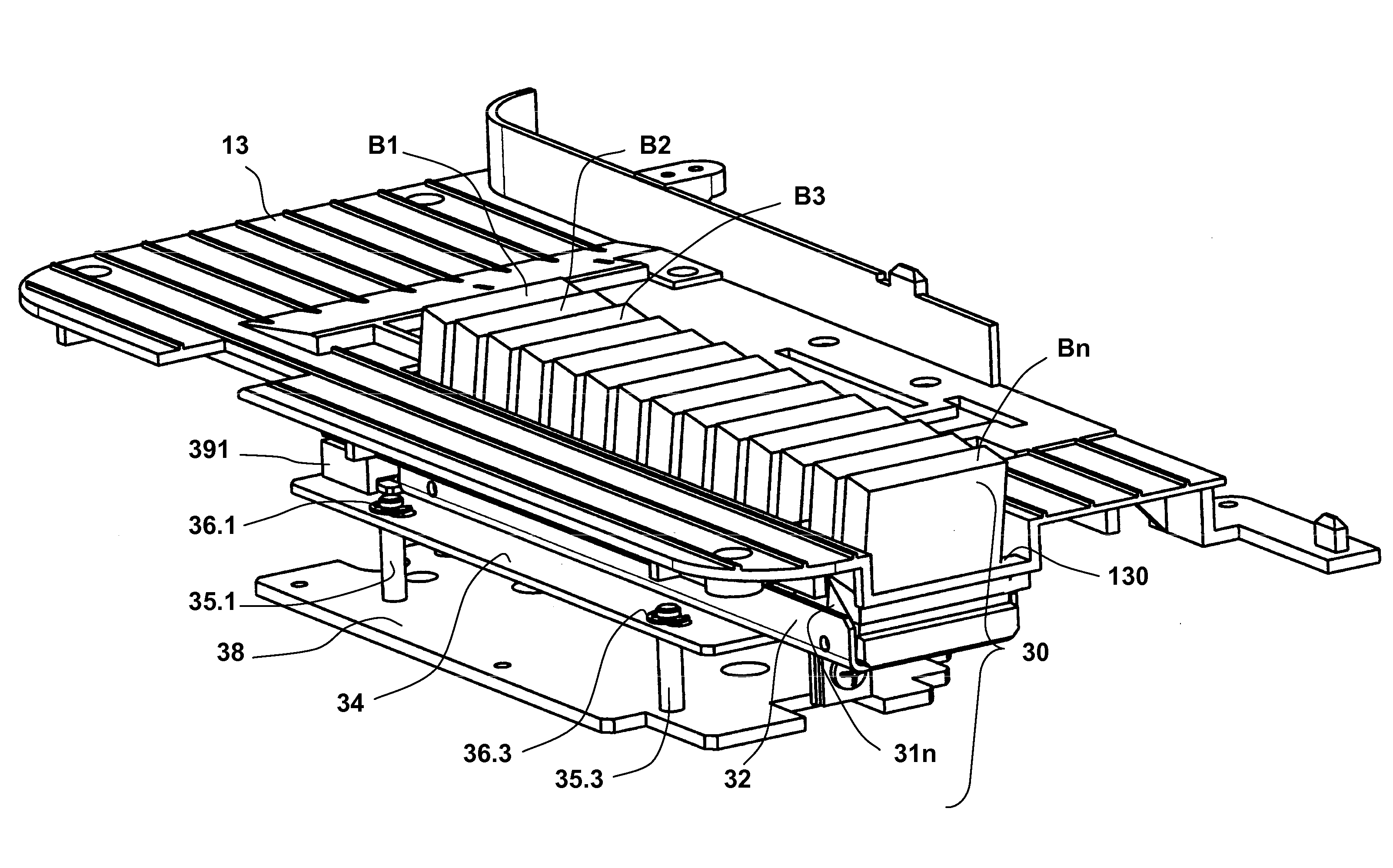
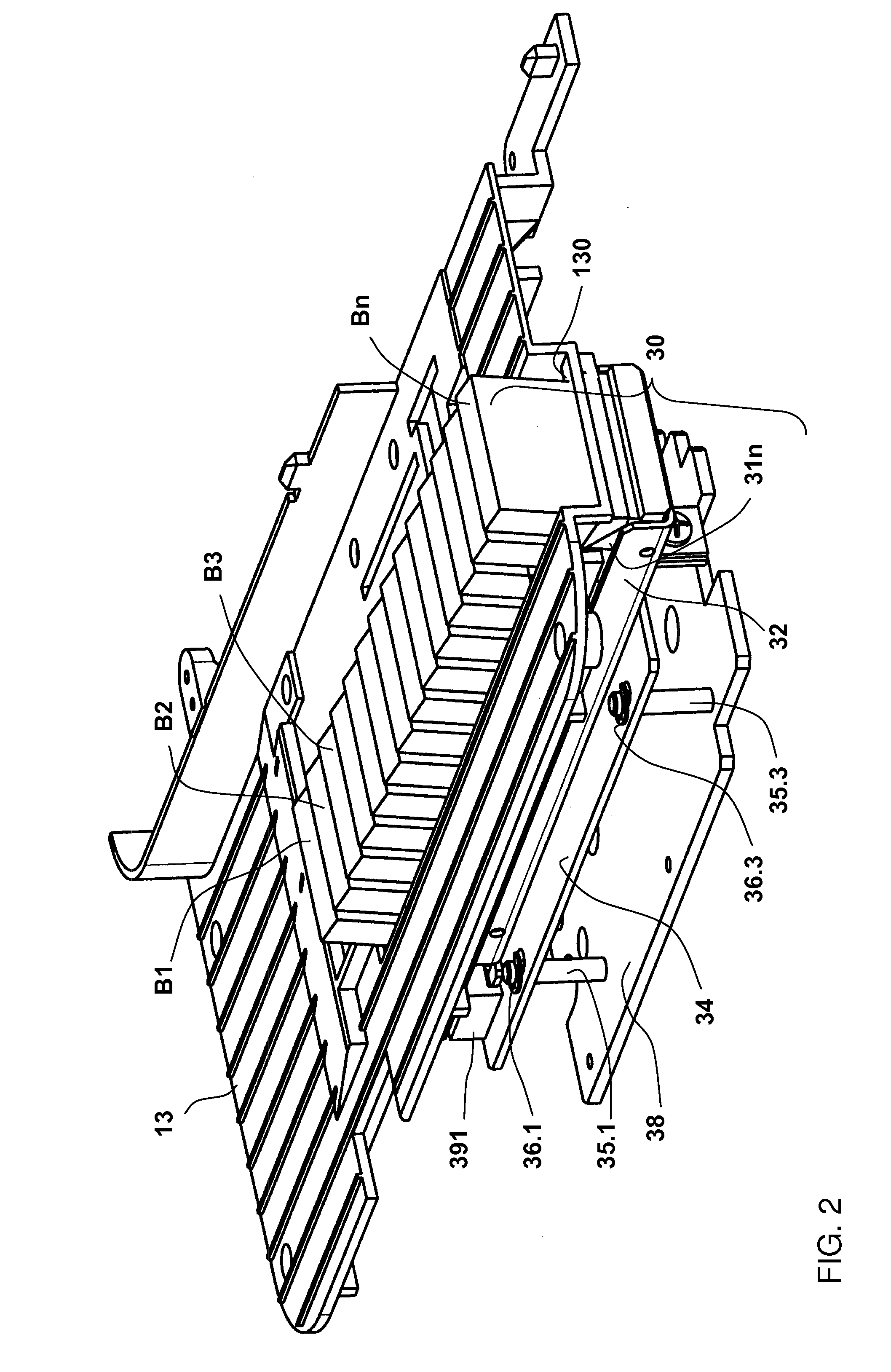
[0043]FIG. 3 shows a front view of the pressing apparatus 30 with the holding carrier 32 having the multiplicity of brush elements B1, B2, B3, . . . , Bi, . . . , Bn and an unsprung slide-in unit 34 to 38. The holding carrier 32 has the multiplicity of brush elements B1, B2, B3, . . . , Bi, . . . , Bn and holders 31.1, 31.2, 31.3 . . . , 31i, . . . 31n for the brush elements. The holders are fastened in the holding carrier 32 which has a base plate 320, from which a first bracket 321 has been machined and is angled away at right angles. The latter and two horns on the mail flow inlet side of the base plate 320 (shown in dashed lines) serve to fasten the unsprung slide-in unit 34 to 38.

[0044]A second bracket 341, which is connected force-lockingly and form-lockingly to the first bracket 321 of the holding carrier 32, is bent away to the bottom from a base plate 34 of the unsprung slide-in unit 34 to 38. A screw connection is produced, for example, through the use of a metal screw 33 ...

second embodiment

[0046]FIG. 4 shows a front view of the pressing apparatus 30′ with a holding carrier 32′ having a multiplicity of brush elements and a sprung slide-in unit. The brush elements likewise are disposed in the form of a brush, as has already been explained by using FIG. 3. The construction of the slide-in unit is also comparable to the embodiment shown in FIG. 3, but with the addition of spiral springs 37.1′, 37.2′, 37.3′ and 37.4′ which are each plugged onto a respective one of bolts 35.1′, 35.2′, 35.3′ and 35.4′. A base plate 34′ in each case has one opening for one of the bolts 35.1′, 35.2′, 35.3′ and 35.4′, as a result of which the bolts can slide through at one end, with a force having to be applied counter to the spring action. The spacer bolts 35.1′, 35.2′, 35.3′ and 35.4′ are fastened at their other end on the floor plate 38′, for example likewise by screwing, riveting or spot welding. An adjusting bolt 392′ and an adjusting piece 391′ form an adjusting device 39′.

[0047]The adjus...

third embodiment

[0048]FIG. 5 shows a front-elevational view of a pressing apparatus 30* having a sprung slide-in unit 34* to 38*. The problem of preventing the permanent deformation of the brush elements while ensuring the secure transport of very thin mail items, in particular franking strips, over a long period of time is solved by providing a so-called dual spring system. The dual spring system on one hand provides the required pressure force, and, on the other hand, optimizes the pressure force such that a remaining deformation of the brush elements B1*, B2*, B3*, . . . , Bi*, . . . , Bn* is prevented.

[0049]The dual spring system consists of the already known spring elements 37* between the base plate 34* and the floor plate 38*, which hitherto served for pressing the holding carrier 32* onto the transport belt, as well as further spring elements 42*, which are arranged between the floor plate 38* and the chassis 42*. Preferably at least one additional spring element would be provided behind ea...


PUM


Abstract

An apparatus for pressing flat materials onto a transport module with a transport belt includes a holding carrier for pressing elements being disposed under a feed table. At least one of the pressing elements is mounted on the holding carrier with a multiplicity of individual resilient or sprung constituent parts, or a multiplicity of pressing elements are disposed on the holding carrier below the transport belt in a transport direction. The pressing elements can protrude through an opening in the feed table, in order to provide suitable pressure from below on the transport belt of the transport module.

Description

CROSS-REFERENCE TO RELATED APPLICATION[0001]This is a continuation-in-part application of U.S. patent application Ser. No. 12 / 252,697, filed Oct. 16, 2008; the application also claims the priority, under 35 U.S.C. §119, of German patent application No. DE 10 2007 060 789.1, filed Dec. 17, 2007; the prior applications are herewith incorporated by reference in their entirety.BACKGROUND OF THE INVENTIONField of the Invention[0002]The invention relates to an apparatus for pressing flat materials onto a transport module of a printing apparatus which is controlled by a microprocessor and has, in a printing position, a printing module which does not move during printing. The flat materials are fed in to the printing apparatus on a feed table and are pressed onto a transport belt in a supporting region counter to the force of gravity. The invention is used in printing apparatuses which are controlled by a microprocessor and is suitable for franking machines and other mail processing units.[...

Claims


Application Information

Patent Timeline
Patent Type & Authority Applications(United States)
IPC IPC(8): B65H5/02B65H5/36
CPCB41J13/12B41J11/007
Inventor HANTEL, ULRICHMUHL, WOLFGANGWOLM, DIETERORTMANN, AXEL
Owner FRANCOTYP POSTALIA
Why Eureka
Try Eureka