Microfluidic systems, devices and methods for reducing background autofluorescence and the effects thereof

a microfluidic system and autofluorescence technology, applied in the field of microfluidic systems, devices, can solve the problems of significantly increasing signal-to-background, reducing cost and improving data quality, and glass substrate materials that are difficult to manufacture into microfluidic chips, so as to reduce autofluorescence, reduce background autofluorescence, and reduce autofluorescence

Inactive Publication Date: 2009-06-04
SCIEX
View PDF2 Cites 27 Cited by
  • Summary
  • Abstract
  • Description
  • Claims
  • Application Information

AI Technical Summary

Benefits of technology

[0009]According to a second embodiment, a microfluidic system and method is disclosed for reducing autofluorescence. The microfluidic system can include a light source for generating an excitation light. The microfluidic system can also include a microscope comprising an objective for focusing the excitation light on a fluid inside a microfluidic channel of a microfluidic chip, wherein the excitation light illuminates the fluid for generating emitted fluorescent light. Further, the microfluidic system can include a shielding comprising an opening. The microfluidic system can also include a first convex lens positioned to receive the emitted fluorescent light and focus the emitted light through the opening of the shielding for eliminating unwanted background autofluorescence. Further, the microfluidic system can include a detector for detecting the light passing through the opening of the shielding
[0010]According to a third embodiment, a method is provided for reducing autofluorescence in a microfluidic system. The method can include generating an excitation light. The method can also include focusing the excitation light on a fluid inside a microfluidic channel of a microfluidic chip, wherein the excitation light illuminates the fluid for generating fluorescent light. Further, the method can include rejecting out-of-focus light for eliminating unwanted background autofluorescence. The method can also include detecting the fluorescent light.
[0011]According to a fourth embodiment, a microfluidic device for reducing autofluorescence is provided. The device can include a microfluidic chip that encloses a microscale channel. The device can also include a support frame connected to the microfluidic chip for supporting the microfluidic chip.
[0012]According to a fifth embodiment, a microfluidic device for reducing autofluorescence is provided. The device can include providing a first thin film including a microscale channel fabricated therein. The device can also include a second thin film connected to the first thin film. Further, the device can include a support frame connected to the first or second thin film for supporting the first or second thin film.
[0016]According to a ninth embodiment, a method for fabricating a microfluidic device having reduced autofluorescence is provided. The method can include providing a microfluidic chip. The method can also include exposing the microfluidic chip to ultraviolet light including a wavelength matching the excitation wavelength used to analyze fluids in the microfluidic chip.
[0017]According to a tenth embodiment, a method for reducing autofluorescence in a microfluidic chip is provided. The method can include providing a microfluidic chip including a deep channel. Further, the method can include generating an excitation light. The method can also include focusing the excitation light on a fluid inside the deep channel. The excitation light can illuminate the fluid for generating fluorescent light. Further, the method can include detecting the fluorescent light.

Problems solved by technology

These systems have resulted in decreased cost and improved data quality.
A primary challenge in the design of microfluidic chips is reducing unwanted background autofluorescence when fluorescence of a reporter molecule in the reaction is used to measure the extent of the reaction.
Glass substrate materials have been used to reduce background autofluorescence, although glass substrate materials can be difficult to manufacture into a microfluidic chip.
However, these polymers still have some autofluorescence, and can significantly increase signal-to-background and decrease the signal-to-noise ratio.

Method used


Image

  • Microfluidic systems, devices and methods for reducing background autofluorescence and the effects thereof
  • Microfluidic systems, devices and methods for reducing background autofluorescence and the effects thereof
  • Microfluidic systems, devices and methods for reducing background autofluorescence and the effects thereof

Examples


Embodiment Construction

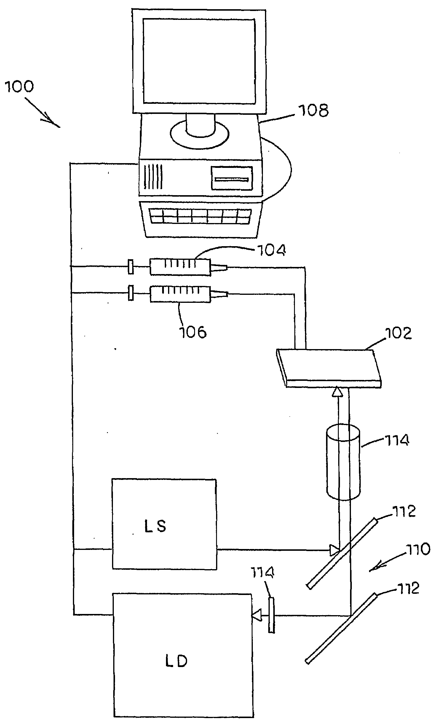
[0034]Microfluidic chips, systems, devices and related methods are described herein which incorporate improvements for reducing background autofluorescence and the effects thereof. These microfluidic chips, systems, devices and methods are described with regard to the accompanying drawings. It should be appreciated that the drawings do not constitute limitations on the scope of the disclosed microfluidic chips, systems, and methods.

[0035]As used herein, the term “autofluorescence” generally refers to the natural, inherent fluorescent light that is emitted by a substrate when the substrate is irradiated with an excitation light.

[0036]As used herein, the term “fluid” generally means any flowable medium such as liquid, gas, vapor, supercritical fluid, combinations thereof, or the ordinary meaning as understood by those of skill in the art.

[0037]As used herein, the term “vapor” generally means any fluid that can move and expand without restriction except for at a physical boundary such ...


PUM


Abstract

According to one embodiment, a microfluidic system and method is disclosed for reducing autofluorescence. The microfluidic system can include a light source for generating an excitation light. The microfluidic system can also include a microscope having an objective for focusing the excitation light on a fluid inside a microfluidic channel of a microfluidic chip. Further, the microfluidic system can include a detector for rejecting out-of-focus light emitted from the microfluidic chip.

Description

CROSS-REFERENCE TO RELATED APPLICATIONS[0001]This application claims the benefit of U.S. Patent Application Ser. No. 60 / 707,386, filed Aug. 11, 2005, the disclosure of which is incorporated herein by reference in its entirety. The disclosures of the following U.S. Provisional Applications, commonly owned and simultaneously filed Aug. 11, 2005, are all incorporated by reference in their entirety: U.S. Provisional Application entitled MICROFLUIDIC APPARATUS AND METHOD FOR SAMPLE PREPARATION AND ANALYSIS, U.S. Provisional Application No. 60 / 707,373 (Attorney Docket No. 447 / 99 / 2 / 1); U.S. Provisional Application entitled APPARATUS AND METHOD FOR HANDLING FLUIDS AT NANO-SCALE RATES, U.S. Provisional Application No. 60 / 707,421 (Attorney Docket No. 447 / 99 / 2 / 2); U.S. Provisional Application entitled MICROFLUIDIC BASED APPARATUS AND METHOD FOR THERMAL REGULATION AND NOISE REDUCTION, U.S. Provisional Application No. 60 / 707,330 (Attorney Docket No. 447 / 99 / 2 / 3); U.S. Provisional Application enti...

Claims


Application Information

Patent Timeline
IPC IPC(8): H05B33/00G01J1/58
CPCB01L3/502707B01L3/502715B01L2200/12B01L2300/0816G01N21/6458B01L2300/0887B01L2300/12G01N21/6428B01L2300/0822
Inventor NEVILL, JOSHUA T.ESPENHAHN, ERIC T.HARTMANN, DANIEL M.VOTAW, GREGORY A.CRENSHAW, HUGH C.
Owner SCIEX
Why Eureka
Try Eureka