
Conformable wide wall angle

Inactive Publication Date: 2009-06-04
USG INTERIORS LLC
View PDF33 Cites 2 Cited by
  • Summary
  • Abstract
  • Description
  • Claims
  • Application Information

AI Technical Summary

Benefits of technology

[0003]The invention provides a wide faced wall angle suitable for use in locations of seismic activity that effectively eliminates or reduces the distortion of the wide face when the angle is installed on uneven or non-planar areas existing in a wall. The invention reduces the degree of buckling to an acceptable level by creating a two-part wide face. The resulting structure can conform to a non-planar wall area without requiring the part of the wide face distal from the wall to stretch or compress to the degree that would otherwise be required.
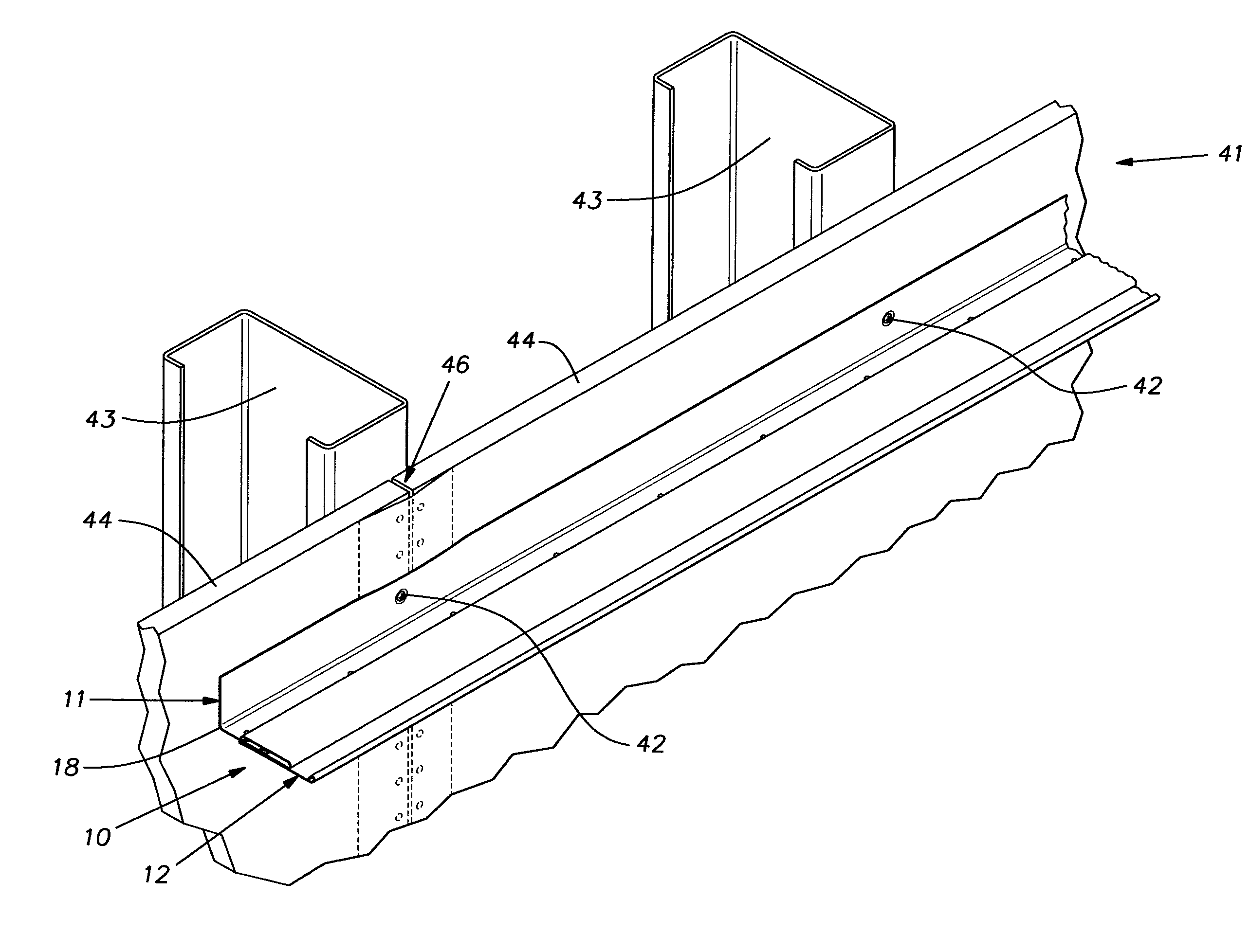
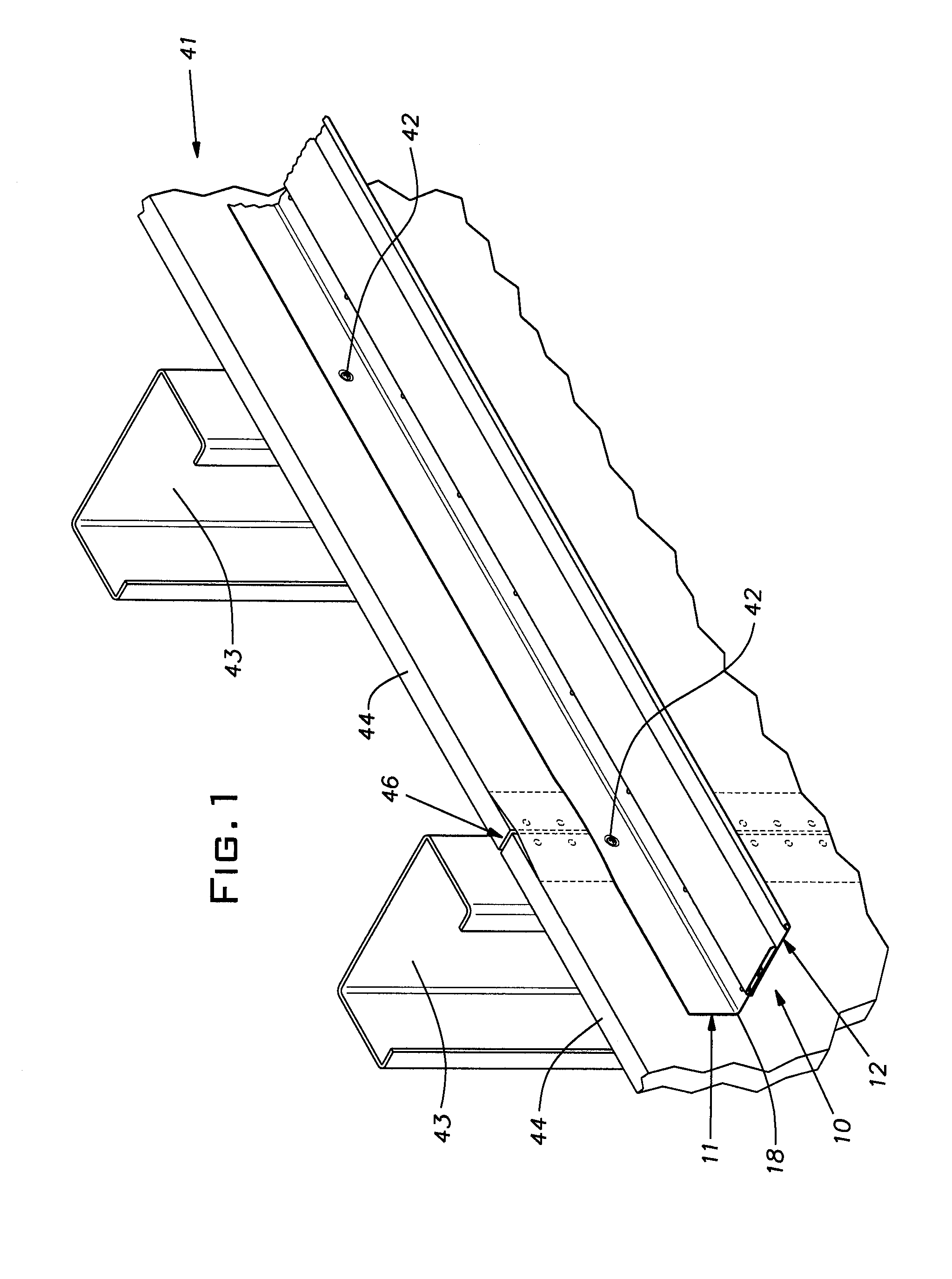
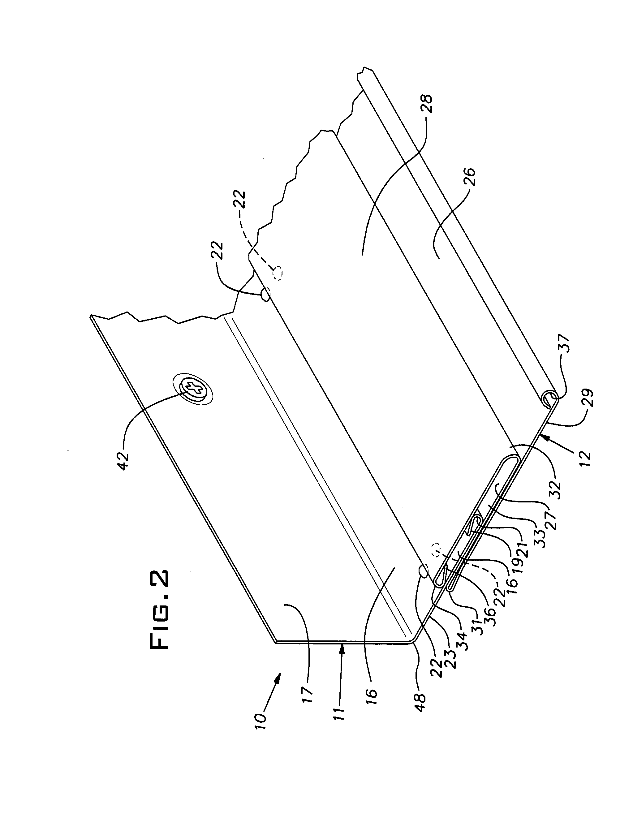
[0004]In the preferred embodiment, the wall angle assembly utilizes a base angle of conventional equal leg proportions and a leg extending strip that telescopes with the horizontal leg of the base. The illustrated base angle has single layer equal length legs while the extension strip is a multi-layer construction that wraps over and frictionally clasps the horizontal base angle leg. This arrangement greatly reduces the strain necessarily imposed on the horizontal face of the unit and effectively isolates this strain from the extension strip. That is, the extension strip is free of the strain imposed on the base angle when the latter is bent to conform to a non-planar wall surface. Further, the extension strip is the most visible part of the wall angle and is in a location to conceal all or a portion of distortions created in the horizontal leg of the base angle. In the disclosed embodiment, the base angle and the extension strip have hemmed edges that cooperate to resist accidental separation as well as distortion from their ideal straight lines.

Problems solved by technology

Conventional wide faced wall angle frequently presents a problem because walls are seldom flat.
However, when a conventional wide faced wall angle is installed over a non-flat joint or other irregularity, the visible face of the angle distorts by buckling up or down out of a horizontal plane.
This distortion is often unacceptable from an appearance standpoint.
Moreover, there appears to be no simple, readily available remedy to conceal or eliminate this buckling action that occurs with conventional seismic wall angle.

Method used


Image

  • Conformable wide wall angle
  • Conformable wide wall angle
  • Conformable wide wall angle

Examples


Embodiment Construction

[0007]A wall angle 10 constructed in accordance with the invention is a two-part assembly comprising a base angle 11 and an extension strip 12. The wall angle 10 is especially suited for seismic applications by virtue of having a relatively wide horizontal side indicated generally at 13. Both the base angle and extension strip components 11, 12 are unitary or one-piece elements preferably made of roll-formed sheet metal, typically steel or, less commonly, aluminum. The metal strips forming these components 11, 12 can be coated, plated or otherwise treated to impart corrosion resistance and whether or not so treated, are usually finish painted for improved appearance. Such treatments and painting are ordinarily done before roll forming of the components 11, 12.

[0008]The base angle 11 and extension strip 12 are provided in standard lengths of, for example, 10 foot or 12 foot or metric equivalent. The base angle 11 and extension strip 12 have their profiles drawn to scale in the figure...


PUM


Abstract

A wide wall angle useful in locations of seismic activity to support ceiling tile and grid tees of a suspended ceiling comprising an assembly of an elongated base angle and an elongated extension strip, the base angle having generally perpendicular legs integral with one another and intersecting at a longitudinally extending corner, one leg being adapted to be fixed against a wall with the corner down, and the other adapted to project horizontally from the wall, the extension strip having a face with greater than the width of the horizontal leg, the extension strip having a multiple layer construction, two layers of the extension strip being held together in close parallel relation by an intermediate web integral with the layers, at least portions of the two layers being arranged to frictionally engage at least a part of the horizontal leg of the base angle spaced from the corner such that the strip can be assembled on and frictionally retained on the horizontal leg of the base angle, the horizontal leg of the base angle being disposed between the two layers of the extension strip.

Description

BACKGROUND OF THE INVENTION[0001]The invention relates to accessories for suspended ceilings and, in particular, to a novel wall angle especially suited for use in locations of potential seismic activity.PRIOR ART[0002]In conventional suspended ceiling installations, wall angle is typically used along the walls to support the edges of ceiling tiles and ends of cross tees. In cases of expected seismic activity, the wall angle can be specified to be significantly wider than the normal width so that the risk of the ceiling tiles or grid elements slipping off during an earthquake of limited magnitude is reduced. Conventional wide faced wall angle frequently presents a problem because walls are seldom flat. Walls regularly deviate from an ideal flat plane for various reasons. A common reason for a wall to depart from a flat plane is the presence of taped joints in drywall type construction particularly where the joints are between non-tapered panel edges. Such joints can be almost imperc...

Claims


Application Information

Patent Timeline
IPC IPC(8): E04B1/98E04B9/06E04B9/18E04B9/30
CPCE04C2003/046E04B9/30
Inventor LALONDE, PAUL D.
Owner USG INTERIORS LLC
Learn More