
Apparatus and method for micro performance tuning of a clocked digital system

a technology of micro-performance and clock rate, applied in error detection/correction, instruments, generating/distributing signals, etc., can solve the problems of reducing system performance, reducing clock rate, and increasing delay in logic state transition time, so as to achieve more time to the core

Inactive Publication Date: 2009-05-28
IBM CORP
View PDF12 Cites 31 Cited by
  • Summary
  • Abstract
  • Description
  • Claims
  • Application Information

AI Technical Summary

Benefits of technology

The patent describes an apparatus and method for optimizing the performance of a microprocessor by dynamically adjusting the clock frequency of the core. This is achieved by using a sensor to detect changes in voltage levels in the core when it is transitioning between states. The sensor triggers adjustments to the clock period to allow more time for the core to complete the transition. The adjusted clock period is determined based on the sensor output and can be faster or slower than the worst-case clock frequency. The method can be applied to a microprocessor with one or more cores, and a separate local voltage power source can be connected to each core for optimal performance. The technical effect of this invention is to improve the speed and performance of microprocessors by optimizing the clock frequency of the core.

Problems solved by technology

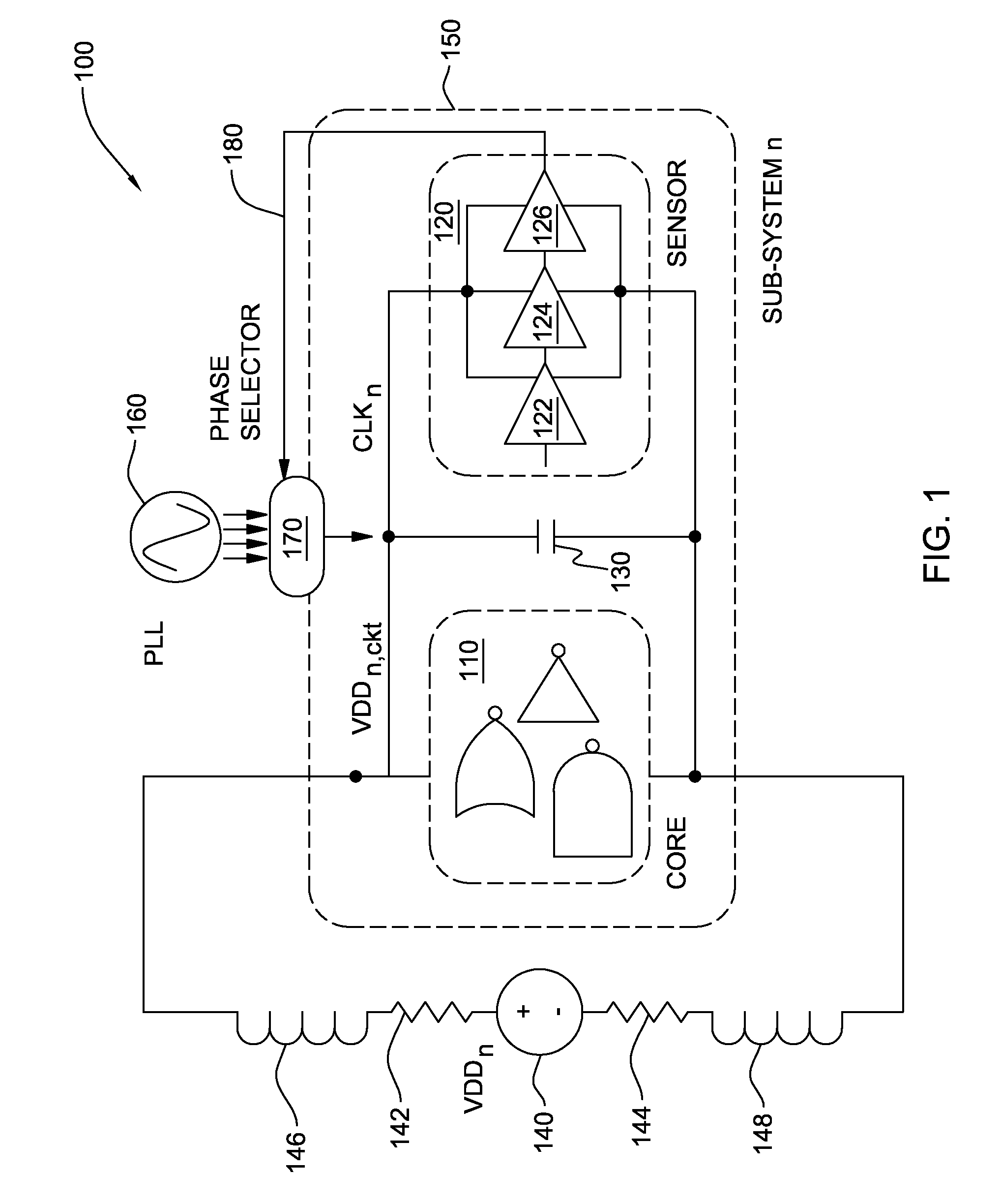
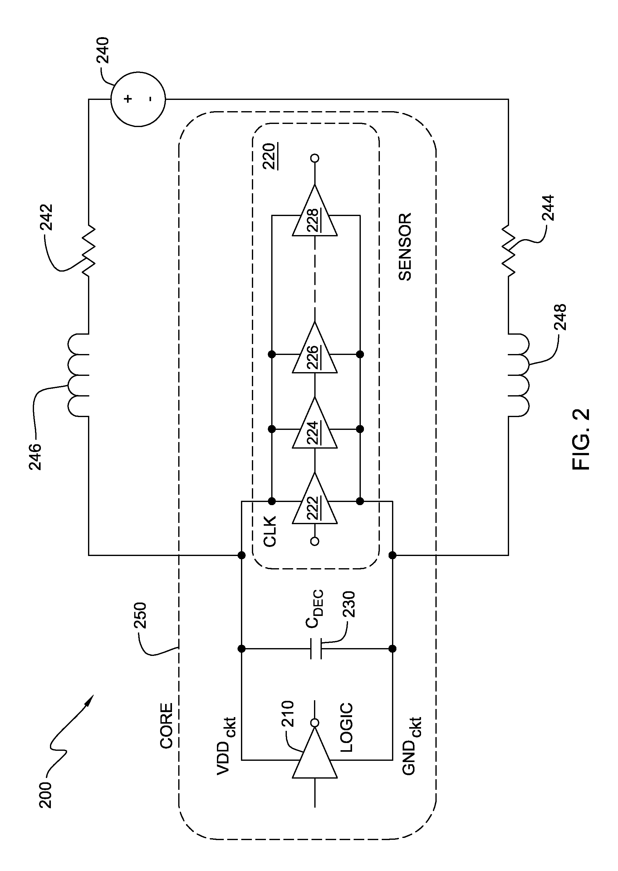
The switching draws a lot of current from the power supply, such that, the system's local power supply voltage and ground voltage are bounced due to limited on-chip decoupling capacitance and non-zero power supply line resistance and inductance.
This voltage bouncing results in insufficient current being provided for the system leading to an increased delay in state transition time for the logic, a lower clock rate and a decrease in system performance.

Method used


Image

  • Apparatus and method for micro performance tuning of a clocked digital system
  • Apparatus and method for micro performance tuning of a clocked digital system
  • Apparatus and method for micro performance tuning of a clocked digital system

Examples


Embodiment Construction

[0018]Reference throughout this specification to “one embodiment,”“an embodiment,” or similar language means that a particular feature, structure, or characteristic described in connection with the embodiment is included in at least one embodiment of the present invention. Thus, appearances of the phrases “in one embodiment,”“in an embodiment,” and similar language throughout this specification may, but do not necessarily, all refer to the same embodiment.

[0019]It will be apparent to those skilled in the art that various modifications and variations can be made to the present invention without departing from the spirit and scope of the invention. Thus, it is intended that the present invention cover the modifications and variations of this invention provided they come within the scope of the appended claims and their equivalents. Reference will now be made in detail to the preferred embodiments of the invention.

[0020]In one embodiment, the present invention provides an apparatus for...


PUM


Abstract

An apparatus and method for micro-tuning an effective clock frequency of a core in a microprocessor. The apparatus includes a microprocessor having at least one core with logic configured to transition between states, a clock signal coupled to the microprocessor, the clock signal having a predetermined clock frequency based on a worst-case clock frequency and a predetermined clock period. The apparatus further including at least one voltage drop sensor coupled to the core, the sensor being configured to generate an output signal for detecting a voltage drop in the core and to determine whether or not the output signal is detected within the clock period and, if the output signal is not detected, the sensor dynamically adjusts the clock period of the clock signal provided to the core to allow more time to complete state transitions, such that, dynamically adjusting the clock period effectively changes an effective core clock frequency.

Description

FIELD OF THE INVENTION[0001]The present invention relates to an apparatus and method for micro performance tuning of a clocked digital system. More particularly, the present invention relates to an apparatus and method for micro-managing the clock distribution to the clocked digital system for optimizing system performance and an effective operating frequency of the digital system.BACKGROUND OF THE INVENTION[0002]A clocked digital system has a regular clock rate or frequency for synchronous data handling. The system's maximum operating frequency is determined by the worst case delay in the system. The worst case delay depends on the synchronous switching of the digital logic in the system. The switching draws a lot of current from the power supply, such that, the system's local power supply voltage and ground voltage are bounced due to limited on-chip decoupling capacitance and non-zero power supply line resistance and inductance. This voltage bouncing results in insufficient curren...

Claims


Application Information

Patent Timeline
Patent Type & Authority Applications(United States)
IPC IPC(8): G06F1/08
CPCG06F1/08
Inventor KIM, DAEIKKIM, JONGHAEKIM, MOON J.MOULIC, JAMES R.
Owner IBM CORP
Learn More