
OFDM packet communication receiver

a packet communication and receiver technology, applied in the field of packet communication receivers, can solve the problems of phase noise, degraded signal quality, and inability to accurately synchronize timing

Inactive Publication Date: 2006-06-06
NIPPON TELEGRAPH & TELEPHONE CORP
View PDF5 Cites 113 Cited by
  • Summary
  • Abstract
  • Description
  • Claims
  • Application Information

AI Technical Summary

Problems solved by technology

In general, when high rate signals are transmitted through wireless channel, signal quality will be degraded because of inter-symbol interference due to multi-path propagation caused by reflection and/or diffraction.
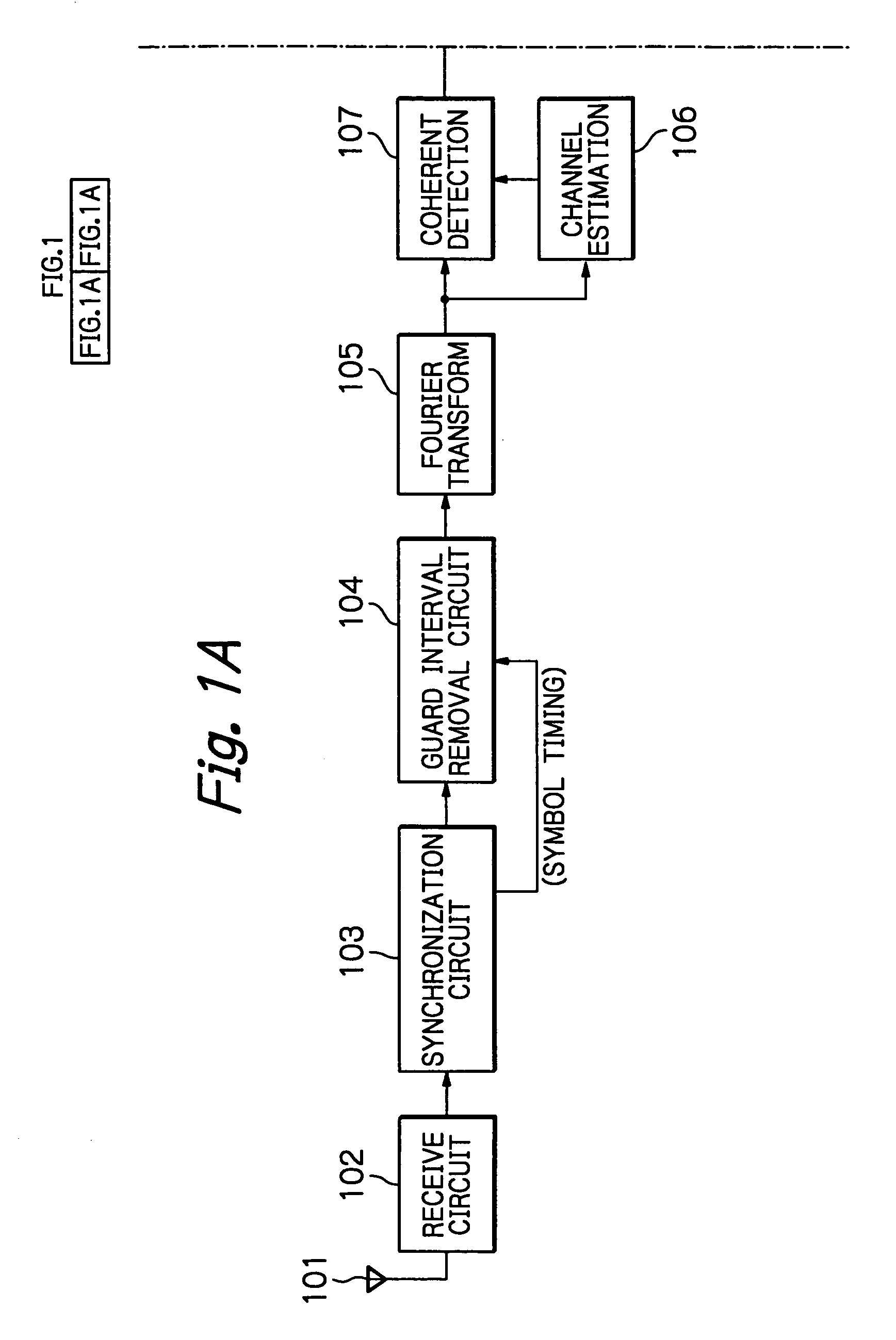
Furthermore, because of the presence of a guard interval, a receiver can demodulate signals with no interference originated in adjacent symbols, even when symbol timing, i.e. FFT window timing, has a small timing error within said guard interval due to noise component and suchlike.
Thus, no accurate timing synchronization, which is essential in single-carrier transmission systems, is required in OFDM systems.
However, when there exists a sampling clock frequency error between a transmitter and a receiver, timing difference between the symbol timing of each OFDM symbol and the FFT window timing depends upon the location of the OFDM symbol in the packet even in a single packet.
The phase noise is the noise which is added to phase component of the received signal due to imperfection of analog devices of both a transmitting circuit in a transmitter and a receiving circuit in a receiver.
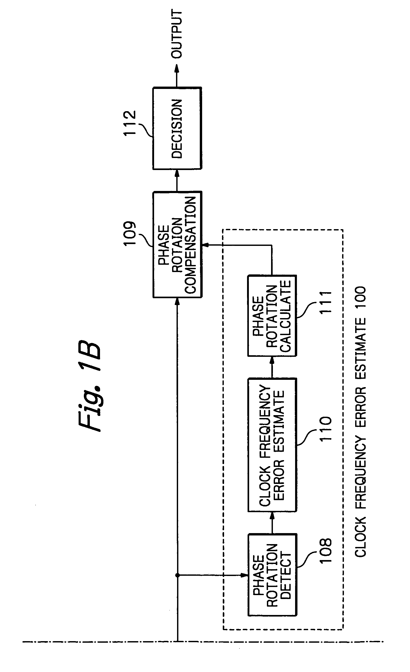
As described above, when sampling clock frequency has an error between a transmitter and a receiver, if coherent detection is carried out with no clock frequency error compensation, a receiver can not detect phase of each subcarrier signal correctly due to phase rotation of each subcarrier signal, and therefore, signal quality is considerably degraded.
However, the control through analog process requires many complicated analog circuits.
Moreover, it is difficult for analog process to realize high compensation accuracy.
Therefore, a prior receiver can not obtain high transmission quality.
In addition, it consumes much power.
However, detected carrier frequency error generally includes some detection error because thermal noise is superimposed on received signals in receiving process which includes frequency conversion, orthogonal detection and others.
Therefore, it is difficult for the above-mentioned carrier frequency compensation process to accurately compensate a carrier frequency error, and transmission quality is degraded due to the phase rotation of each subcarrier signal originated in c

Method used


Image

  • OFDM packet communication receiver
  • OFDM packet communication receiver
  • OFDM packet communication receiver

Examples


tenth embodiment

[0223]FIG. 10 shows tenth embodiment, which is a modification of FIG. 9, and is directed to claim 10. The same numerals in FIG. 10 as those in FIG. 9 show the same members.

[0224]FIG. 10 embodiment comprises a weighting circuit 1001 and a smoothing circuit 1002. The operation of a residual carrier frequency error detector 1003 is essentially the same as that of the residual carrier frequency error detector 902.

[0225]It is assumed in FIG. 10 that carrier frequency and clock frequency are synchronized with each other in a transmitter, and further, clock frequency in a receiver is controlled so that it synchronizes with carrier frequency.

[0226]A weighting circuit 1001 receives an output of the coherent detection circuit 107, an output of the channel estimator 106, and an output of a phase rotation estimator 904.

[0227]The weighting circuit 1001 receives a part or all of the detected signals of the coherent detection circuit 107. The weighting circuit 1001 compensates phase rotation in th...

eleventh embodiment

[0233]FIG. 11 shows eleventh embodiment, which is a modification of FIG. 9 and is directed to claim 11. The same numerals in FIG. 11 as those in FIG. 9 show the same members.

[0234]The embodiment of FIG. 11 has a pilot signal extractor 1101. The operation of a residual carrier frequency error detector 1102 is essentially the same as that of the residual carrier frequency error detector 902.

[0235]It is assumed in FIG. 11 that known pilot signals are transmitted by using a part of subcarriers in OFDM signals.

[0236]Further, it is assumed in FIG. 11 that carrier frequency and clock frequency are synchronized with each other in a transmitter, and clock frequency is controlled in a receiver so that it synchronizes with carrier frequency.

[0237]The pilot signal extractor 1101 receives output signals of the coherent detection circuit 107, and extracts signal components of pilot signals in said output signals.

[0238]The residual carrier frequency error detector 1102 receives said pilot signal, ...

twelfth embodiment

[0243]FIG. 12 shows twelfth embodiment, which is a modification of FIG. 9, and is directed to claim 12.

[0244]The same numerals in FIG. 12 as those in FIG. 9 show the same members.

[0245]The embodiment of FIG. 12 comprises a pilot signal extractor 1201, a weighting circuit 1202, a smoothing circuit 1203, and a residual carrier frequency error detector 1204. The operation of the residual carrier frequency error detector 1204 is essentially the same as that of the residual carrier frequency error detector 902.

[0246]It is also assumed in FIG. 12 that known pilot signals are transmitted by using a part of subcarriers.

[0247]Further, it is assumed that carrier frequency and clock frequency are synchronized with each other in a transmitter, and clock frequency in a receiver is synchronized with carrier frequency.

[0248]The pilot signal extractor 1201 extracts pilot signals in output signals of the coherent detection circuit 107.

[0249]The weighting circuit 1202 receives a pilot signal extracte...


PUM


Abstract

In an OFDM packet communication receiver, the deterioration of received signal quality is suppressed, even when carrier frequency error and/or clock frequency error exists between a transmitter and a receiver, and/or phase noise and/or thermal noise is superimposed to a received signal in a receiver.

Description

BACKGROUND OF THE INVENTION[0001]The present invention relates to a packet communication receiver used in OFDM (Orthogonal Frequency Division Multiplexing) digital wireless communication system. In particular, it relates to an OFDM receiver for demodulating OFDM signals accurately with little process delay and high transmission efficiency, even when there is a sampling clock frequency error and / or a carrier frequency error between a transmitter and a receiver, and / or received signals are affected by phase noise and / or thermal noise.DESCRIPTION OF THE RELATED ART[0002]An OFDM system is a kind of multicarrier transmission system which divides an original high rate signal stream into a plurality of low rate parallel signal streams and transmits them simultaneously. In an OFDM system, each subcarrier is closely located orthogonally with one another on the frequency axis. In general, when high rate signals are transmitted through wireless channel, signal quality will be degraded because ...

Claims


Application Information

Patent Timeline
IPC IPC(8): H04J11/00H04L27/26
CPCH04L27/2662H04L27/2695H04L27/266H04L27/2657
Inventor KUMAGAI, TOMOAKIMORIKURA, MASAHIROMIZOGUCHI, MASATO
Owner NIPPON TELEGRAPH & TELEPHONE CORP
Learn More