
Magnetic disk substrate and magnetic disk thereof

Inactive Publication Date: 2009-05-07
SHOWA DENKO KK
View PDF8 Cites 5 Cited by
  • Summary
  • Abstract
  • Description
  • Claims
  • Application Information

AI Technical Summary

Benefits of technology

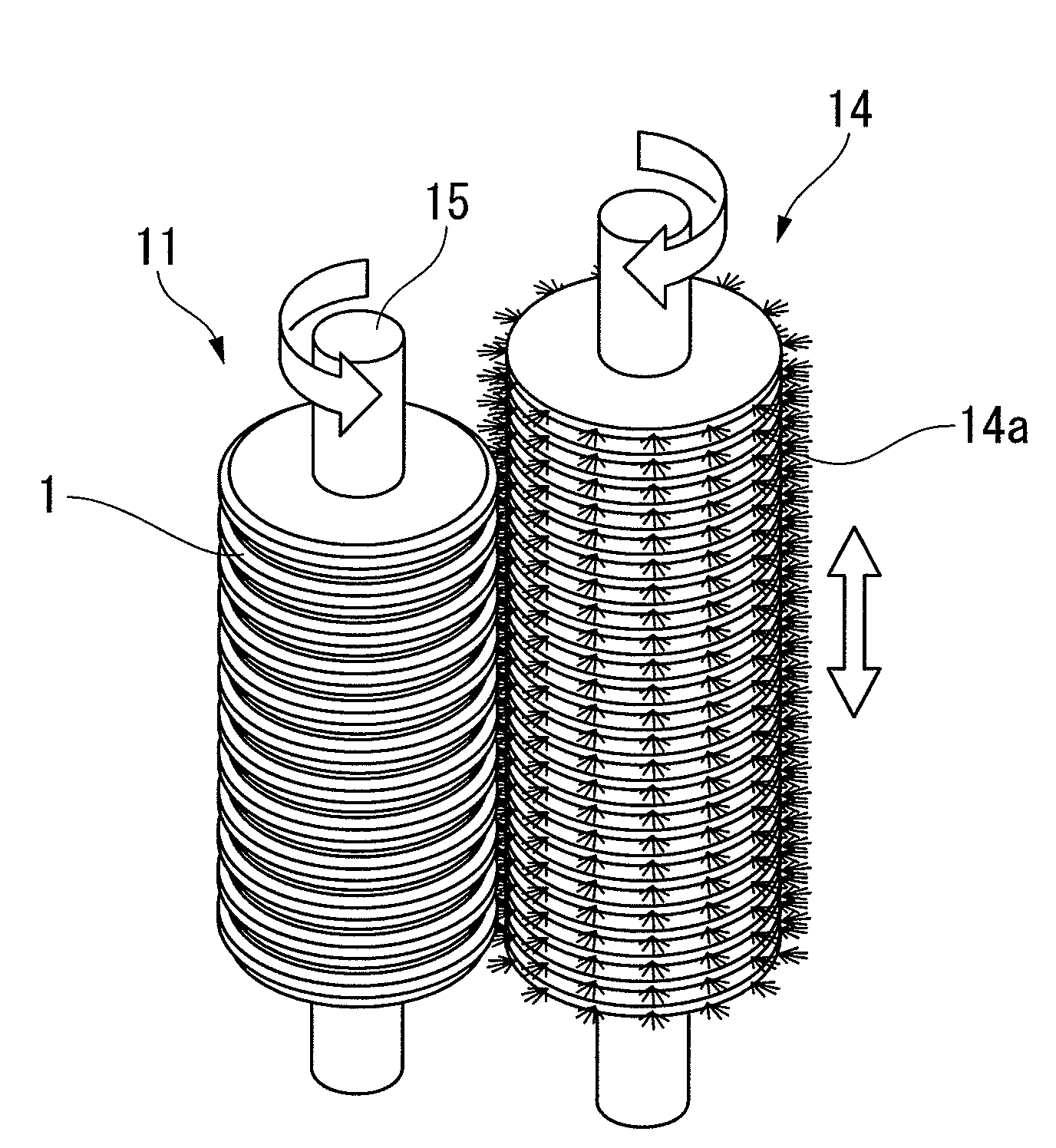
[0014]When a magnetic disk is produced, a primary coat, a magnetic recording layer, a protective layer, or the like are formed successively on the above-described substrate in order. Also, if micro-particles are present on the surface of the protective layer, the “burnishing treatment” is conducted thereon. In this burnishing treatment, the surface of the protective layer is lightly polished, for example, by pressing a moving lapping tape on the surface of the protective layer with a contact wheel made of rubber. By way of this treatment, the micro-particles present on the surface of the protective layer can be removed, and the floating rate of the magnetic head can be made much smaller.
[0016]The present invention was achieved in order to solve the above-described problem. The object of the present invention is to provide a magnetic disk substrate which can improve the yield in the magnetic disk production using silicon substrates, prevent errors or head crashes when reading or writing, and achieve much lower flying height of the magnetic head, so it can be compatible with much higher recording densification. Also, the object of the present invention is to provide a magnetic disk utilizing the same.
[0017]The present inventors studied the above-described problems, and discovered that it is necessary not only to prevent the silicon substrate, which is materially fragile, from cracking or chipping, but also to prevent the generation of the dusts thereon in the producing process of the magnetic disks by controlling the shape of the circumferential portion of this silicon substrate. This is such that the yield in magnetic disk production using silicon substrates can be improved, an error or head crash when reading or writing can be prevented, and a much lower magnetic head flying height can be achieved, so it can be compatible with a much higher recording density. Finally, this discovery resulted in the present invention.
[0019]According to the present invention, by processing the outer circumferential portion of the silicon substrate into the above-defined shape, not only the cracks or chips of the silicon substrate, which is materially fragile, can be prevented, but also the generation of the dusts thereon in the production process of the magnetic disks can be prevented. Consequently, particles of dusts or the like can be prevented from adhering to the surface of the magnetic disk, the production yield of the magnetic disk can be improved, the occurrence of errors or head crashes can be prevented when reading or writing, and it is possible for the magnetic head to fly thereover at a much lower height. Then, this makes it possible for the magnetic disk to be compatible with a much higher recording-densification.

Problems solved by technology

However, when the lapping tape scrapes against the outer circumferential portion of the silicon substrate in the above-described burnishing process, particle dust is likely to generate from this lapping tape, and the generated particles will possibly remain on the surface of the magnetic disks.
Then, the particles adhering to the surface of the magnetic disk will cause an error or head crash when reading or writing, so such magnetic disks having particles thereon are excluded in the final quality inspection.

Method used


Image

  • Magnetic disk substrate and magnetic disk thereof
  • Magnetic disk substrate and magnetic disk thereof
  • Magnetic disk substrate and magnetic disk thereof

Examples


Embodiment Construction

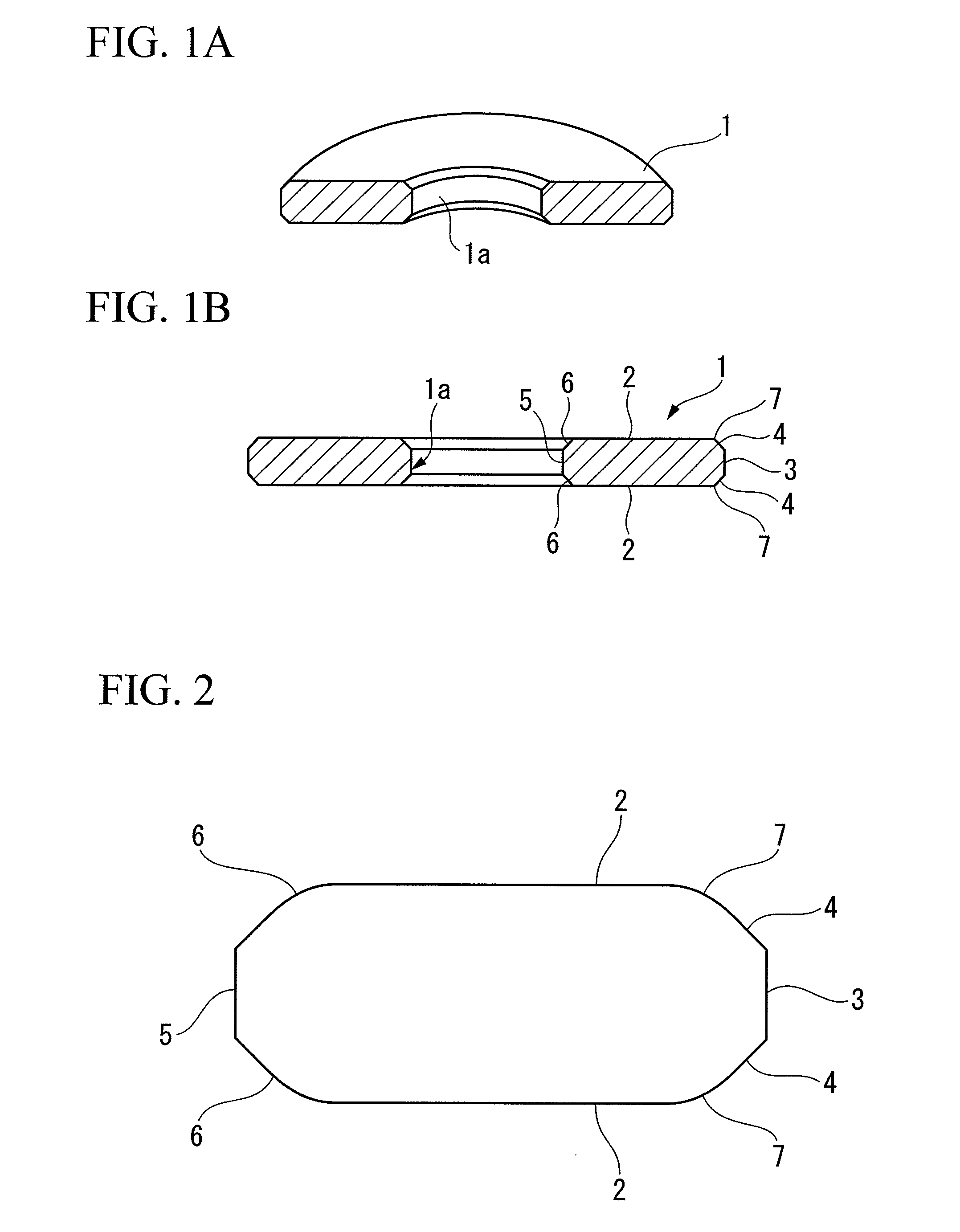
[0030]Hereinafter, the magnetic disk substrate and magnetic disk thereof according to the present invention will be described in detail by using figures. It should be understood that some parts featured in the present invention are enlarged in the figures for the purpose of explicitly describing their features, and their scale ratios or the like do not always reflect actual ratios. In addition, surface-profiling for setting the defined points can be achieved by using a commercially available surface-profiler, and a “CONTRACER CP400”, produced by MITSUTOYO CORPORATION is used for surface-profiling in the present invention.

(Magnetic Disk Substrate)

[0031]First, the magnetic disk substrate of the present invention is described.

[0032]In FIG. 1 and FIG. 2, a magnetic disk substrate using a silicon substrate 1 of the present invention is shown. FIG. 1A is a perspective view showing a cross-section of the silicon substrate 1. FIG. 1B is a cross-sectional view of the silicon substrate 1. FIG...


PUM


Abstract

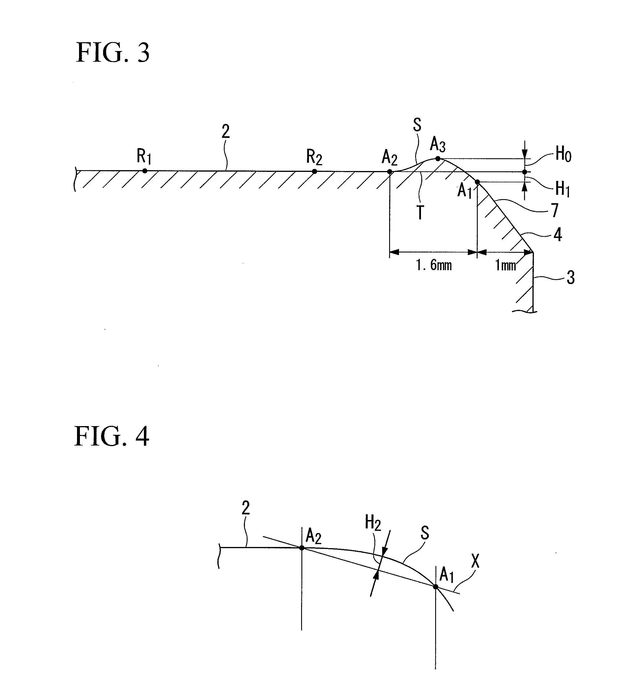
The object of present invention is to provide a magnetic disk substrate which uses a silicon substrate, in which chamfered surfaces are provided between the main surfaces of the silicon substrate and the outer circumferential surface; a ski-jump value H0 where H0≦0 μm, representing the distance from the basal level to point A3; a roll-off value H1 where H1≧−0.2 μm and H1≦0.0 μm, representing the distance from the basal level to point A1; a tag-off value H2 where H2≧0 μm and H2≦0.012 μm, representing the maximum displacement of the border line of the main surface with respect to the line A1 to A2; curved surfaces are provided between the main surfaces and the chamfered surfaces; and the curvature radius R of the curved surface where R≧0.013 mm and R≦0.080 mm.

Description

[0001]This application claims the priority of Japanese Patent Application No. 2005-364545, filed Dec. 19, 2005, and the priority benefit of U.S. Provisional Application No. 60 / 753,418, filed on Dec. 27, 2005, the contents of which are incorporated herein by reference.TECHNICAL FIELD[0002]The present invention relates to a magnetic disk substrate formed by using a silicon substrate, and a magnetic disk utilizing this magnetic disk substrate.BACKGROUND ART[0003]In recent years, the storage capacity of a magnetic recording medium continues to increase as all sorts of IT products are developed. In particular, with regard to a magnetic disk apparatus such as a hard disk drive (HDD) which plays an important role as an external storage apparatus for a computer, its recording capacity and its recording density continue to increase from year to year. This is why a development of a magnetic disk which can record in a much higher density has been expected. On the other hand, a small and shock-...

Claims


Application Information

Patent Timeline
IPC IPC(8): G11B5/62
CPCG11B5/82G11B5/7315G11B5/73911
Inventor MACHIDA, HIROYUKIAIDA, KATSUAKI
Owner SHOWA DENKO KK
Learn More