
Curved display panel and method for manufacturing the same

a display panel and curved technology, applied in the field of display panels, can solve the problems of low stickiness of adhesive, easy generation of air bubbles, high stickiness of solid adhesive, etc., and achieve the effects of avoiding stress concentration of the first glass plate, high stickiness, and improving product yield of the curved display panel

Active Publication Date: 2012-11-06
OPTRONIC SCI LLC
View PDF18 Cites 99 Cited by
  • Summary
  • Abstract
  • Description
  • Claims
  • Application Information

AI Technical Summary

Benefits of technology

[0008]The present invention relates to a curved display panel and a method for manufacturing the curved display panel that can improve product yield.
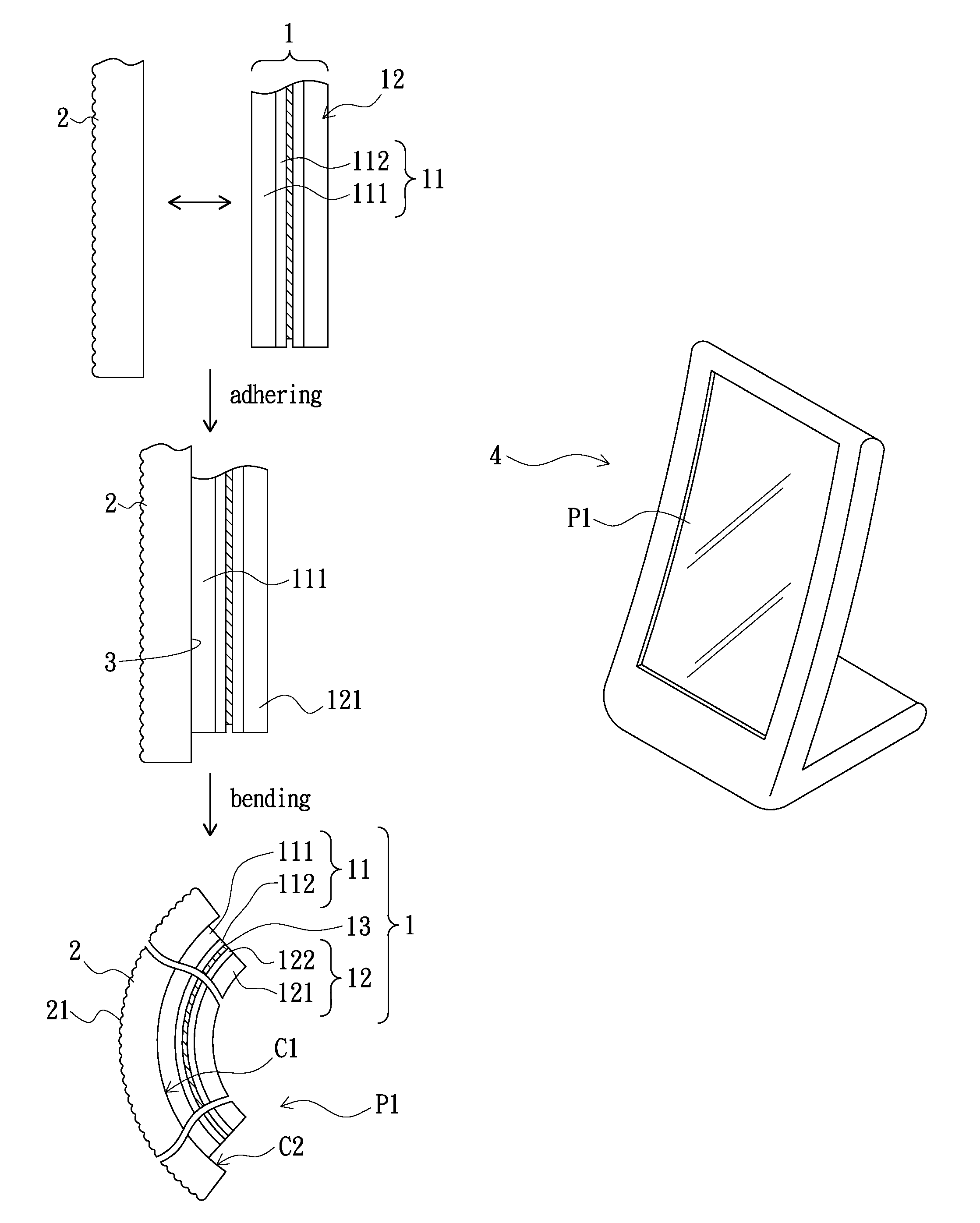
[0011]In the curved display panel and the method for manufacturing the curved display panel of the present invention, the display module having the first glass plate and the first fixing substrate are aligned and adhered firstly, and then the first fixing substrate is curved by exerting the force to act on first fixing substrate so as to bend the display module together with the first fixing substrate. In the process of bending the first glass plate, the force does not act on the first glass plate directly, but acts on the first fixing substrate to bend the first glass plate. As such, stress concentration of the first glass plate can be avoided, and thus the display module can be protected and product yield of the curved display panel can be improved. In addition, in the present invention, the adhering material for adhering the first glass plate to the first fixing substrate includes the solid adhesive and the liquid adhesive. The solid adhesive and the liquid adhesive have various properties. The solid adhesive has high stickiness, but air bubbles are easily generated when using the solid adhesive. The liquid adhesive has low stickiness, but air bubbles are not easily generated when using the liquid adhesive. The combination of the solid adhesive and the liquid adhesive can improve the stickiness and the product yield.

Problems solved by technology

The solid adhesive has high stickiness, but air bubbles are easily generated when using the solid adhesive.
The liquid adhesive has low stickiness, but air bubbles are not easily generated when using the liquid adhesive.

Method used


Image

  • Curved display panel and method for manufacturing the same
  • Curved display panel and method for manufacturing the same
  • Curved display panel and method for manufacturing the same

Examples


first embodiment

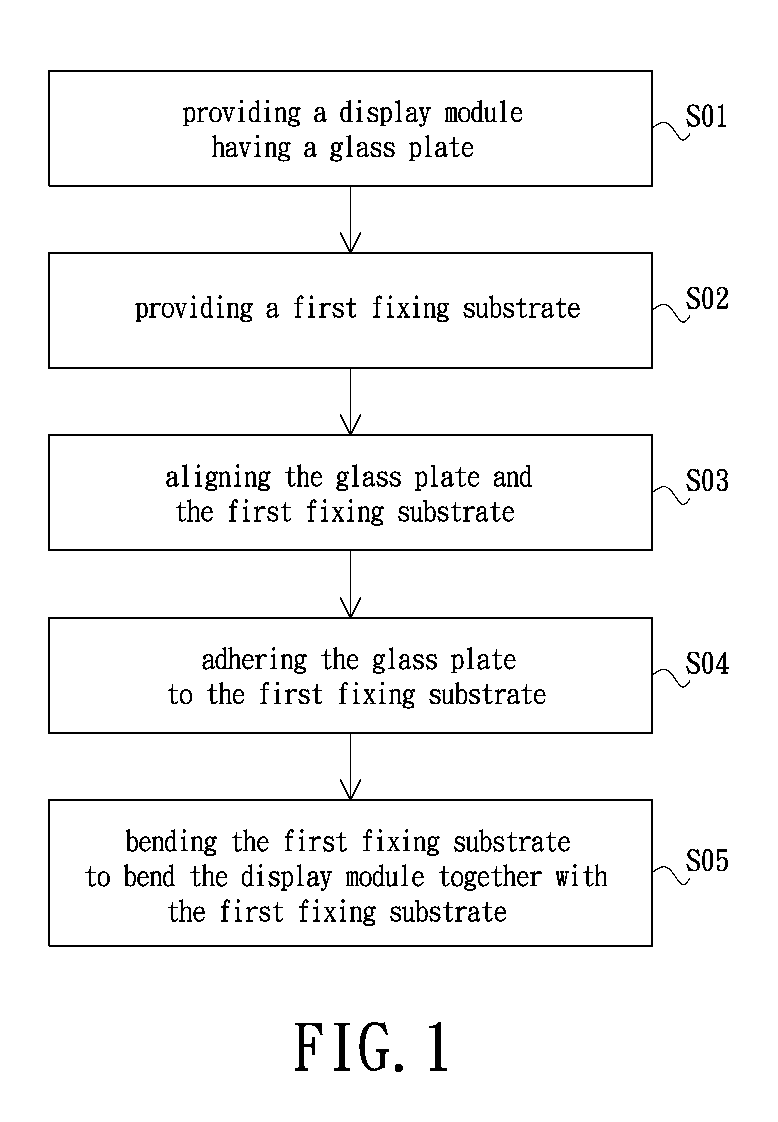
[0023]FIG. 1 is a flow chart of a method for manufacturing a curved display panel according to the present invention. The method for manufacturing the curved display panel includes steps S01˜S05. Hereinafter, the method would be described with FIG. 1 and other FIGS.

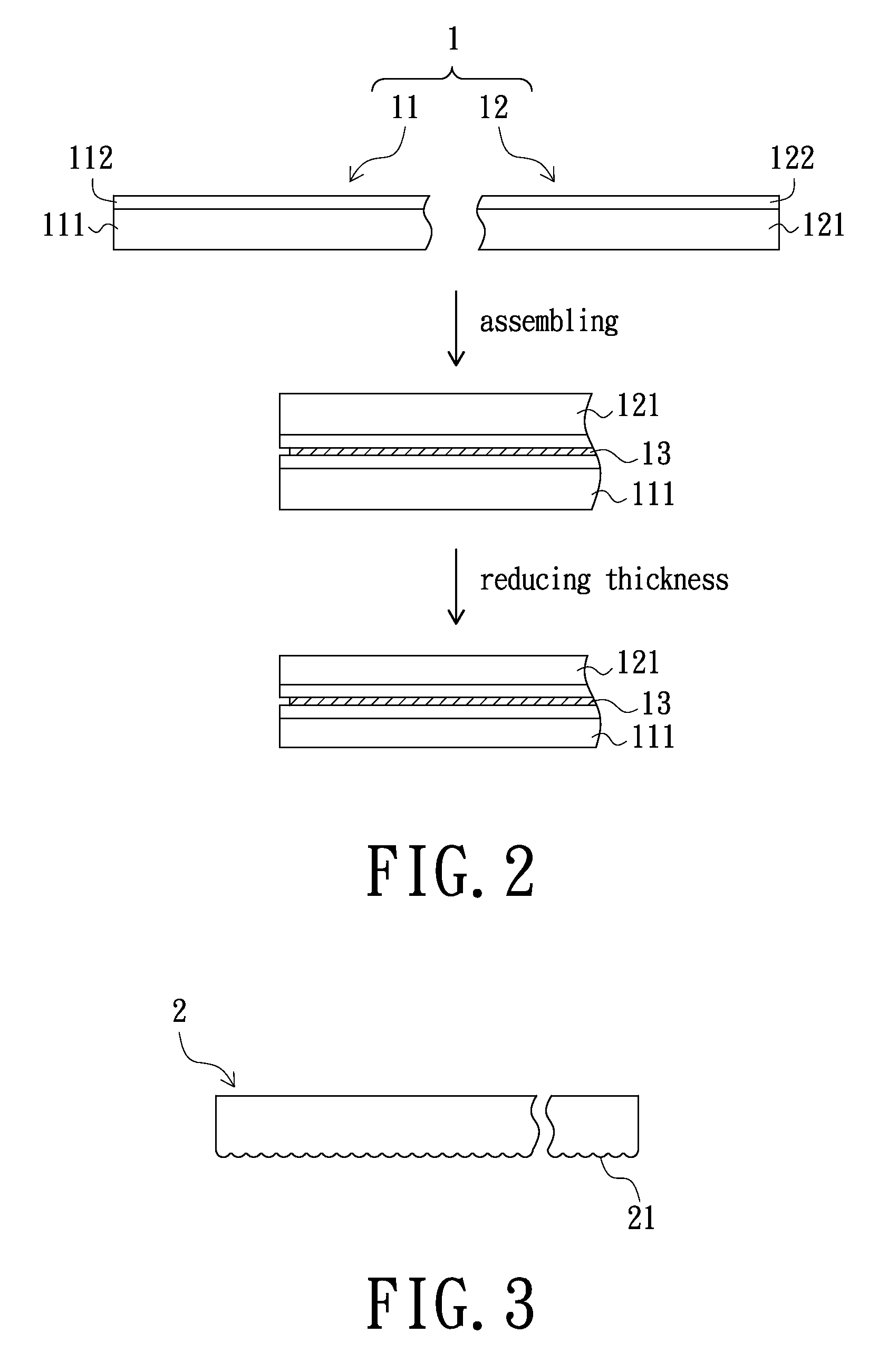
[0024]Referring to FIG. 2, in the step S01, a display module 1 having a glass plate 111 or 121 is provided. Hereinafter, the glass plate 111 is named as a first glass plate 111, and the glass plate 121 is named as a second glass plate 121. The display module 1 of the present invention has a glass plate, and the display module 1 is not limited to a special one. For example, the display module 1 can be a liquid crystal display module, an organic light-emitting diode display module, an electronic paper display module or a light emitting diode display module. In the first embodiment, the display module 1 is the liquid crystal display module for an exemplary purpose.

[0025]The display module 1 includes a first substrate 11 and ...

fifth embodiment

[0040]FIG. 9 shows a curved display panel P3 according to the present invention. The curved display panel P3 is similar in principle to the curved display panel P1, and the difference lies in that the curved display panel P3 further includes a second fixing substrate 6, and that a second glass plate 121 has a third curved surface C3. The second fixing substrate 6 has a fourth curved surface C4 facing the third curved surface C3. The above-mentioned adhering material is further connected between the third curved surface C3 and the fourth curved surface C4. Curvature radiuses of the third curved surface C3 and the fourth curved surface C4 are such as in the range from 10 millimeters to 500 millimeters. The third curved surface C3 and the fourth curved surface C4 are a concave surface and a convex surface respectively that mate with each other. A material of the second fixing substrate 6 is the same as that of a first fixing substrate 2, and it will not be repeated here. In addition, s...

sixth embodiment

[0042]FIG. 10 shows a curved display panel P4 according to the present invention. The curved display panel P4 is similar in principle to the curved display panel P2, and the difference lies in that the curved display panel P4 further includes a second fixing substrate 6′, and that a second glass plate 121′ has a third curved surface C3′. The second fixing substrate 6′ has a fourth curved surface C4′ facing the third curved surface C3′. The above-mentioned adhering material is further connected between the third curved surface C3′ and the fourth curved surface C4′. Curvature radiuses of the third curved surface C3′ and the fourth curved surface C4′ are such as in the range from 10 millimeters to 500 millimeters. The third curved surface C3′ and the fourth curved surface C4′ are a concave surface and a convex surface respectively that mate with each other. A material of the second fixing substrate 6′ is the same as that of a first fixing substrate 2′, and it will not be repeated here....


PUM

PropertyMeasurementUnit
thicknessaaaaaaaaaa
curvature radiusaaaaaaaaaa
thicknessesaaaaaaaaaa

Abstract

A curved display panel includes a display module, a first fixing substrate and an adhering material. The display module has a first glass plate. The first glass plate has a first curved surface. The first fixing substrate has a second curved surface facing the first curved surface. The adhering material is connected between the first curved surface and the second curved surface.

Description

BACKGROUND[0001]1. Field of the Invention[0002]The present invention relates to a display panel, and more particularly to a curved display panel and a method for manufacturing the curved display panel.[0003]2. Description of the Related Art[0004]Because flat panel display devices have advantages of light in weight, small in size, low in power consumption and non-radiation, the flat panel display devices have gradually replaced the cathode ray tube display devices and utilized in various electronic products.[0005]There are many types of the flat panel display devices, such as liquid crystal display devices, organic light emitting diode display devices, electronic paper display devices and light emitting diode display devices. Taking the liquid crystal display device as an example, the liquid crystal display includes a liquid crystal display module and a backlight module. The liquid crystal display module mainly includes a color filter substrate, a thin film transistor substrate and a...

Claims


Application Information

Patent Timeline
Patent Type & Authority Patents(United States)
IPC IPC(8): H05K5/00H05K1/00H05K1/03G02F1/1333H01J9/26G11B5/48
CPCG02F1/133305G02F1/133502G02F2001/133354G02F2202/28G02F1/133354
Inventor WU, JER-YAOKUO, HAN-PINGSU, CHENG-YICHWU, JONG-WENLIU, YU-CHENCHEN, CHIH-WEI
Owner OPTRONIC SCI LLC
Learn More