
Multiplexed Communication System and Multiplexed Communication Method

a communication system and multi-channel technology, applied in the field of multi-channel techniques, can solve the problems of reducing the efficiency of band use, increasing the cumbersomeness and delay time of processing, and unable to efficiently use the network band

Inactive Publication Date: 2009-04-23
NEC CORP
View PDF7 Cites 23 Cited by
  • Summary
  • Abstract
  • Description
  • Claims
  • Application Information

AI Technical Summary

Benefits of technology

[0009]In, e.g., CIP, a packet having a large size is fragmented. In a narrow-band network, this suppresses a fluctuation in transmission delay of small time-critical packets, which is caused by transmission delay of large packets. In a network having a relatively wide band as in the 3GPP / LTE communication technique, however, overhead of headers occurs due to the fragmentation, resulting in degradation in the band use efficiency.
[0011]In these methods, if data is transferred using a protocol such as UDP without flow control in the upper layer, the transmission node one-sidedly controls the transfer amount. It is therefore impossible to efficiently transfer packets in accordance with the use states (congestion states) of reception nodes and, more particularly, radio channels. That is, burst communication occurs. Since each reception node needs to have a buffer for burst communication, the receiving-side platform (memory capacity and processing performance) may increase.
[0012]It is therefore an exemplary object of the invention to make it possible to multiplex packets and transfer a multiplexed packet by extending an existing protocol instead of inserting a new protocol.

Problems solved by technology

This may increase the cumbersomeness and delay time in processing.
Additionally, since the packet transfer amount cannot be controlled in accordance with the use states of radio channels, it is impossible to efficiently use the network band.
In a narrow-band network, this suppresses a fluctuation in transmission delay of small time-critical packets, which is caused by transmission delay of large packets.
In a network having a relatively wide band as in the 3GPP / LTE communication technique, however, overhead of headers occurs due to the fragmentation, resulting in degradation in the band use efficiency.
Hence, a popular IP network cannot directly be applied.
System construction by carriers and, more particularly, channel selection between nodes may be restricted, affecting the installation locations or coverage areas.
It is therefore impossible to efficiently transfer packets in accordance with the use states (congestion states) of reception nodes and, more particularly, radio channels.

Method used


Image

  • Multiplexed Communication System and Multiplexed Communication Method
  • Multiplexed Communication System and Multiplexed Communication Method
  • Multiplexed Communication System and Multiplexed Communication Method

Examples


second exemplary embodiment

Effects of Second Exemplary Embodiment

[0105]As described above, in this exemplary embodiment, destination user information, multiplex flag positions, and the G-TEID of a group to which the destination users belong are registered in correspondence with each other by user management information. Only user packets having the same G-TEID are multiplexed into one multiplexed packet. For these reasons, even when a plurality of correspondence relationships are generated between the destination users and multiplex flag positions, it is possible to specify each destination user using an appropriate correspondence relationship for each multiplexed packet. Hence, the number of destination users to which packets can be transferred by the multiplexed communication system can easily be increased.

Extension of Exemplary Embodiments

[0106]In the above exemplary embodiments, an example has been described in which the remaining storage capacity of the entire reception buffer of the reception processing...


PUM


Abstract

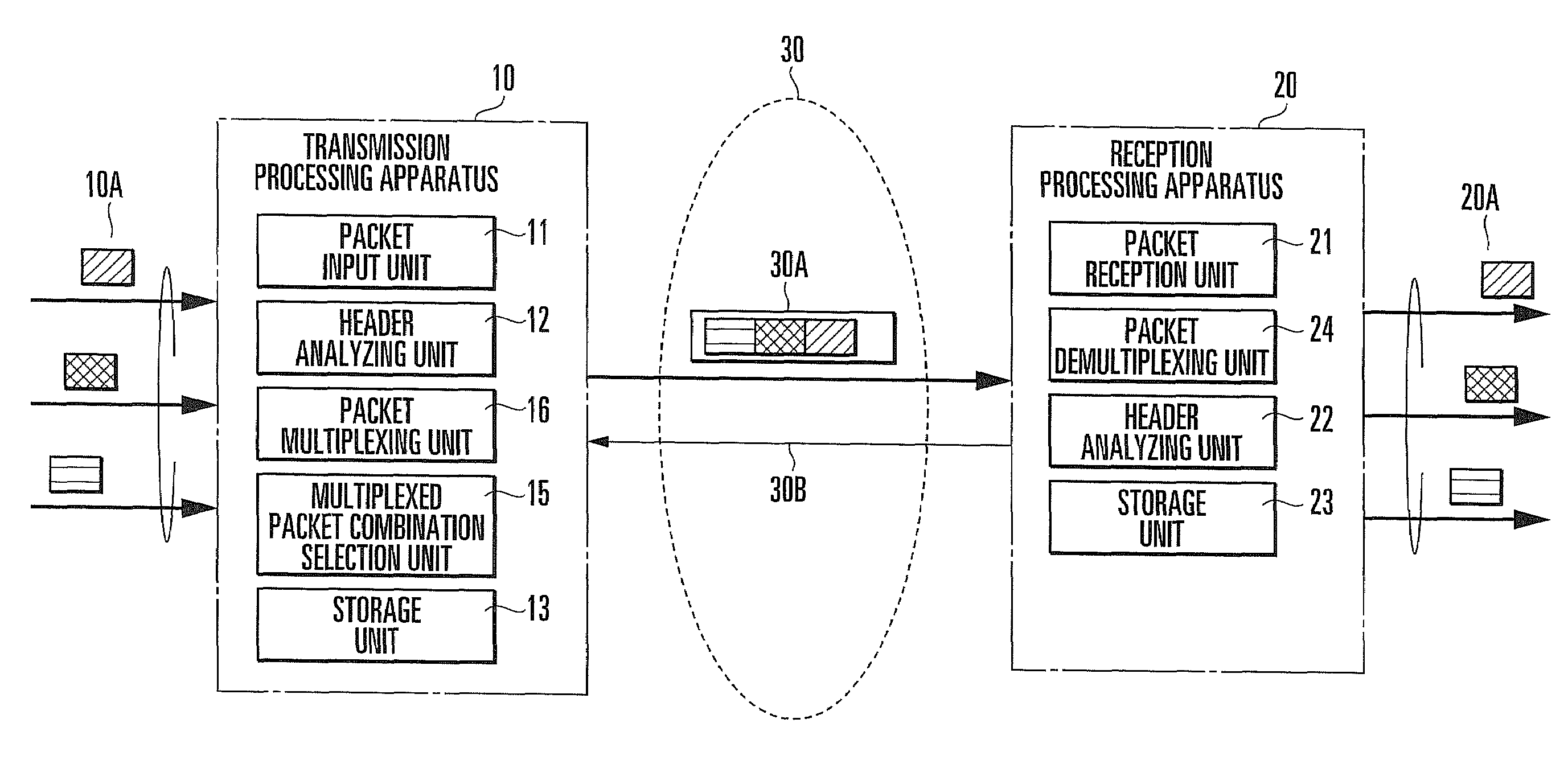
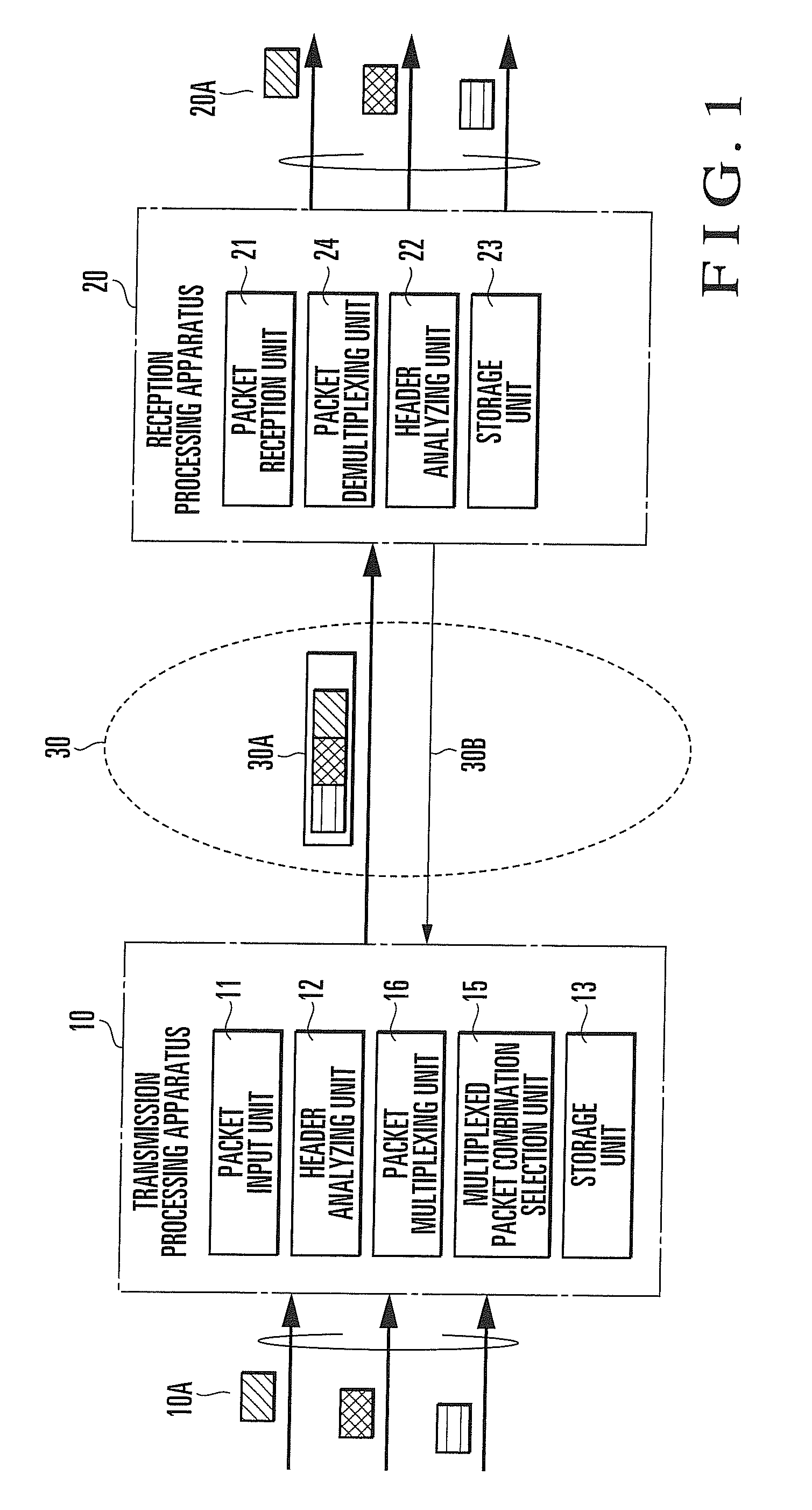
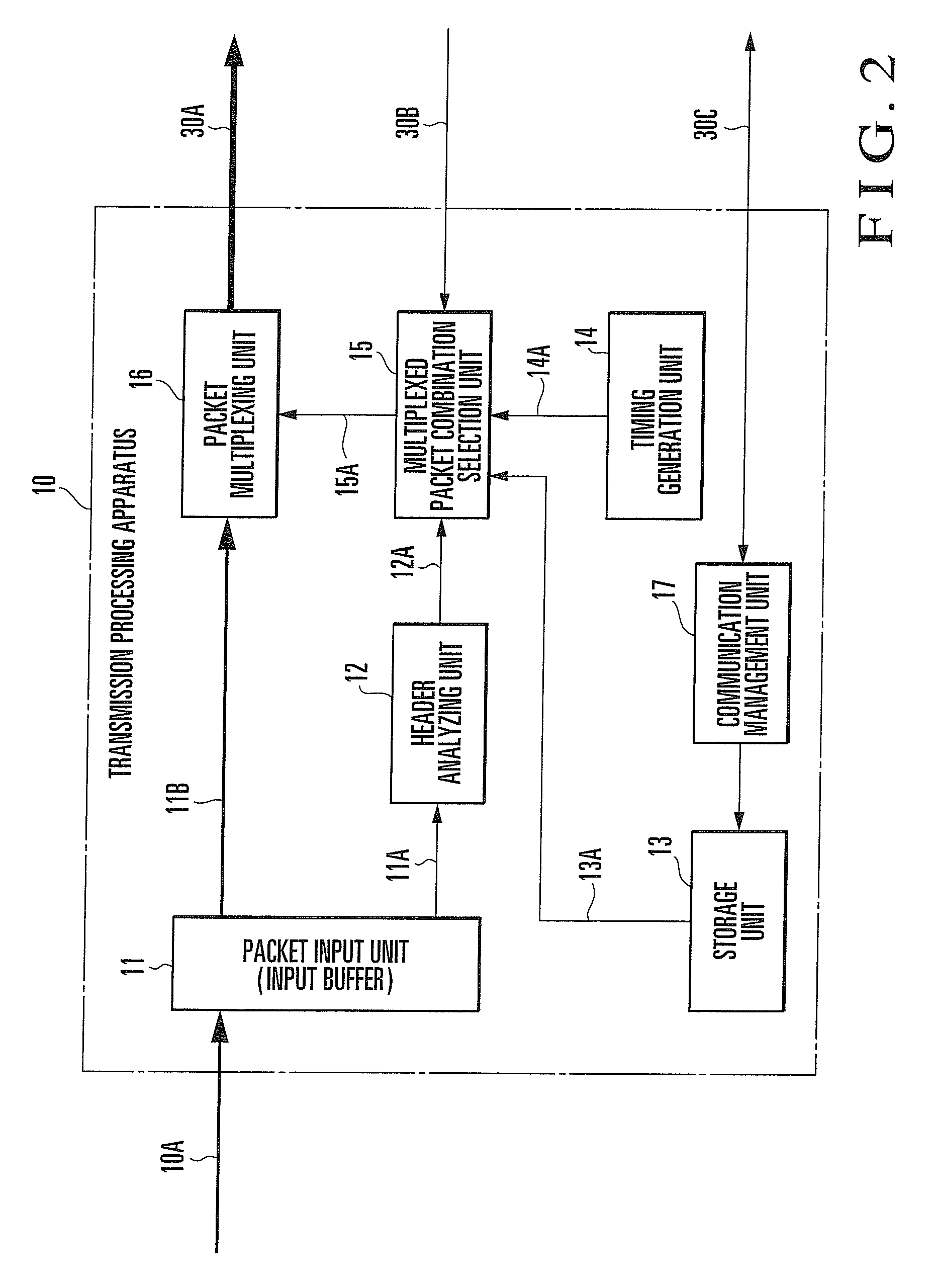
A transmission processing apparatus selects, based on flow control information, user packets to be multiplexed, stores the user packets in the payload of a multiplexed packet based on the position order of multiplex flags corresponding to destination users, stores a multiplex flag group in which only the multiplex flags of the user packets are set in the header of the multiplexed packet, and transmits the multiplexed packet. A reception processing apparatus extracts the multiplex flag group from the header of the received multiplexed packet, transmits flow control information according to the storage state of a reception buffer to the transmission processing apparatus, demultiplexes the user packets from the payload of the multiplexed packet, extracts destination user information corresponding to the set multiplex flags from user management information, and outputs the user packets to the destination users corresponding to the user management information.

Description

[0001]This application is based upon and claims the benefit of priority from Japanese patent application No. 2007-274850, filed on Oct. 23, 2007, the disclosure of which is incorporated herein in its entirety by reference.BACKGROUND OF THE INVENTION[0002]The present invention relates to a multiplexing technique and, more particularly, to a packet multiplexing technique of multiplexing packets and transferring a multiplexed packet.[0003]The IP (Internet Protocol) which has been spread widely among computer networks transfers an Internet diagram from a transmission source host to a destination host but does not support sequencing or flow control. This protocol also transfers data in a size complying with a request from a host application.[0004]The LTE (Long Term Evolution) communication technique which is defined by 3GPP (3rd Generation Partnership Project) as one of high-speed data communication specifications for portable phones has suggested to transfer a user IP packet having the ...

Claims


Application Information

Patent Timeline
Patent Type & Authority Applications(United States)
IPC IPC(8): H04W8/00H04L47/267H04L47/30H04L47/43
CPCH04L12/5602H04L47/30H04W92/12H04W92/045H04W28/10
Inventor INUMARU, TADAYOSHI
Owner NEC CORP
Learn More