
Wire wrapped pressure vessels

a wire-wrapped, pressure vessel technology, applied in vessel construction details, manufacturing tools, mechanical equipment, etc., can solve the problems of low fracture toughness, high cost of premium resin, and processing requirements, and achieve high strength

Active Publication Date: 2009-04-16
WIRETOUGH CYLINDERS
View PDF28 Cites 38 Cited by
  • Summary
  • Abstract
  • Description
  • Claims
  • Application Information

AI Technical Summary

Benefits of technology

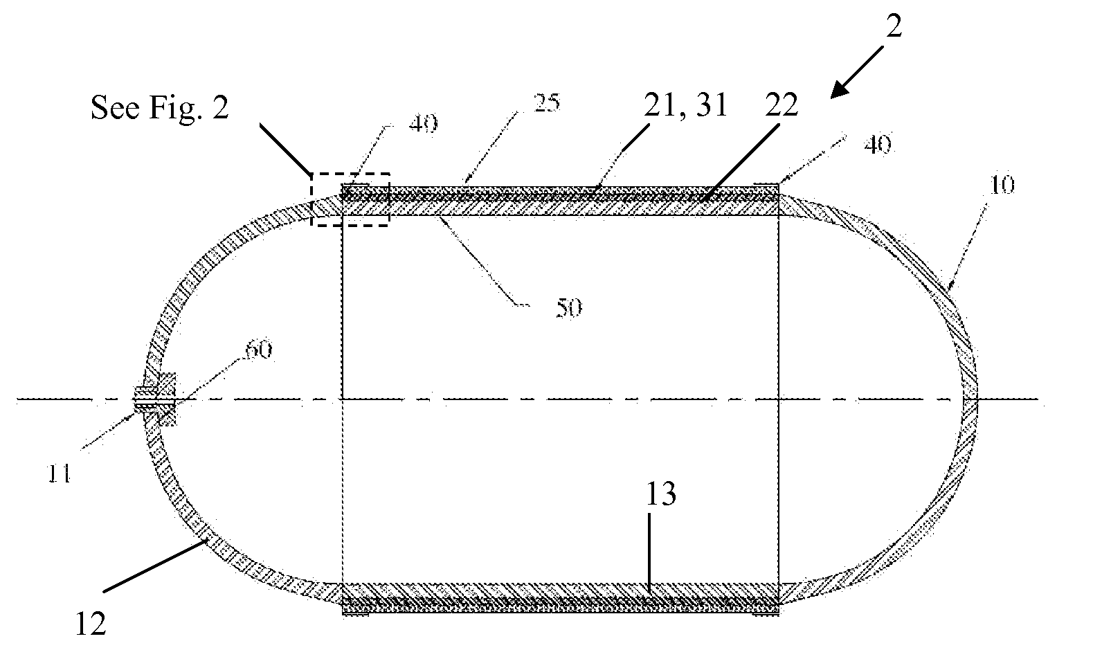
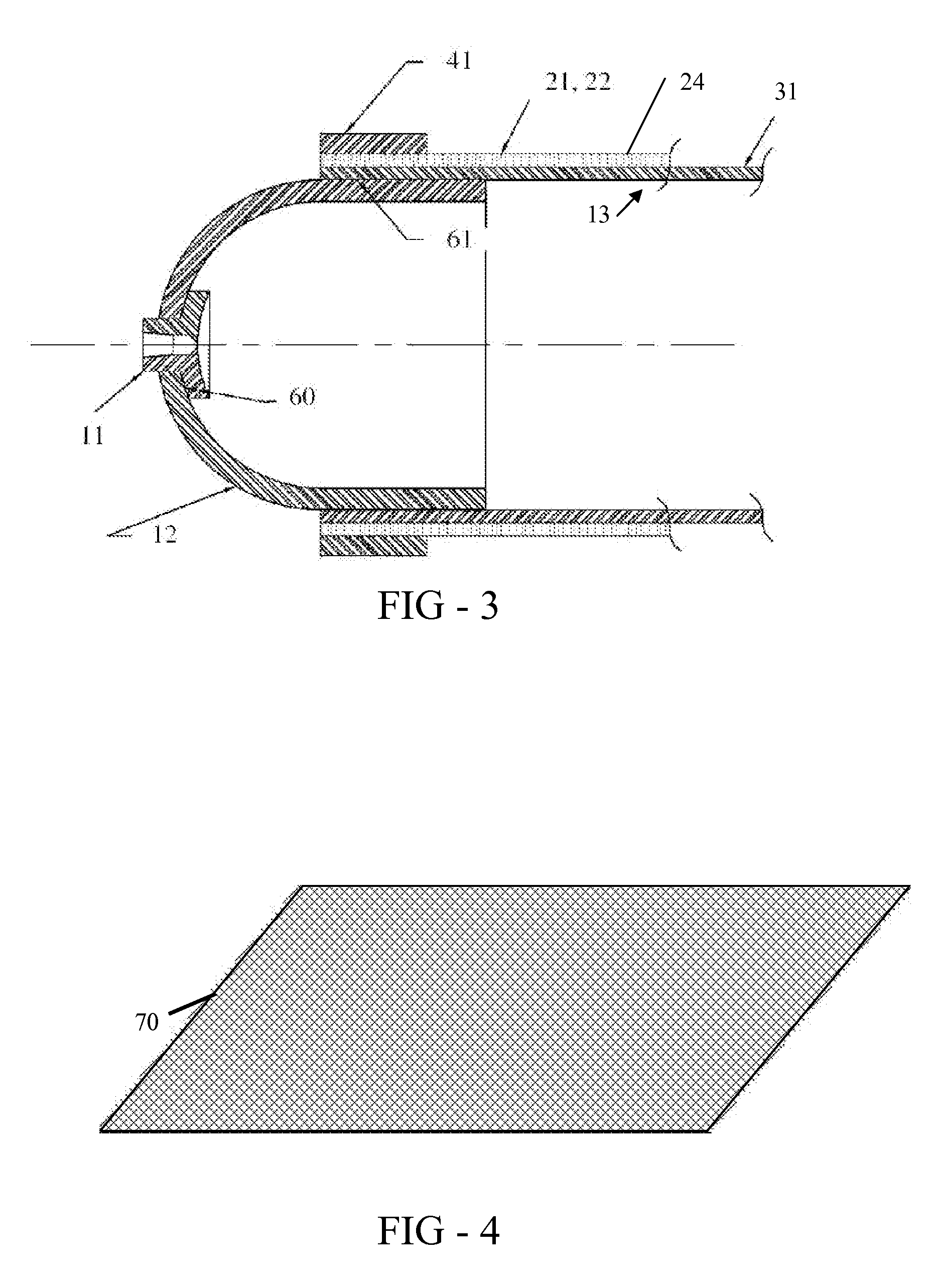
[0013]For circumferential reinforcement, the metal wire runs substantially circumferentially on the cylindrical portion of the vessel only. The wrap may comprise of one or more substantially flat tapes, each tape has multiple metal wire filaments with or without other fibers, all running substantially parallel to each other. The winding density of reinforcing wires is preferably higher on inner layers compared to outer layers with respect to the core of the vessel. The inner wraps on the cylindrical section of the vessel extends farther along the longitudinal axis of the vessel compared to subsequent outer wraps. The metal wires are covered with a polymer having more than 5% elongation at break and can have embedded metal powders such as zinc or aluminum which provide cathodic corrosion protection.
[0017]The pressure vessel which has a core made of steel or steel alloys may have a cathodic protection by the use of an aluminum alloy sheet or wire or wire net in electrical or direct conductive contact with the outer surface of the metal tank and subsequently wrapped with high strength fibers

Problems solved by technology

There are however two disadvantages with these ceramic fibers.
First is the cost as a premium resin and special processing are required to maximize the mechanical properties of glass or carbon fiber reinforced composites.
Secondly, the composite has almost no plastic ductility thus low fracture toughness which makes the structure highly sensitive to minor surface defects or damage.

Method used


Image

  • Wire wrapped pressure vessels
  • Wire wrapped pressure vessels
  • Wire wrapped pressure vessels

Examples


Embodiment Construction

[0023]Description of pressure vessels extends to several designs such as spherical vessels, vessels with a cylindrical section in the middle with dome or other shaped ends as shown in FIG. 1, pressure cylinders such as gun barrel, hydraulic cylinders and other similar structures. The present invention discloses a pressure vessel (2) having a core (10) made of metal or polymer with an opening and wrapped with reinforcing high strength fibers (21, 22). The fibers comprise of metal wires (21) with or without other fibers (22) such as fiberglass or carbon fibers. The metal wires (21) have strength in the range 2000 to 6000 MPa, preferably in the 2000 to 4000 MPa range. For improved impact resistance and toughness the metal wires (21) will have a ductility of more than 20 percent reduction in area (RA) at tensile fracture. The metal wires (21) will be in the diameter range of 0.10 mm to 2 mm and may be round, flat or flat with rounded corner. Wires (21) of different diameters and cables ...


PUM

PropertyMeasurementUnit
diameteraaaaaaaaaa
elongation at breakaaaaaaaaaa
diameteraaaaaaaaaa

Abstract

A pressure vessel (2) for the storage of fluid has a core (10) made of metal or polymer and is wrapped either completely or partially from outside with a high strength fibers (21, 22) for reinforcement wherein one of the reinforcing fibers is a metal wire (21) of a single filament or cables of multi filaments having strength from 2000 MPa to 6000 MPa. The wire has a plastic ductility of over 20% in reduction in area (RA) at tensile fracture. The metal wire (21) is made of steel or nickel or titanium or their respective alloys. The core (10) of the vessel (2) is first wrapped with a resin covered ceramic fibers such as carbon, fiberglass and subsequently wrapped with the metal wire (21) with or without other fibers (22). The metal wires (21) can be of different diameters in parallel or cabled forms.

Description

RELATED APPLICATIONS[0001]This patent application claims priority to provisional application No. 60 / 980268 entitled “Pressure Vessels for Ground Vehicles” filed on Oct. 16, 2008.TECHNICAL FIELD[0002]This invention relates to high pressure containers or vessels for holding liquids or gasses.BACKGROUND OF THE INVENTION[0003]The scope of a pressure vessel applies to any container having pressure differential between its inside and outside. The contained energy is proportional to the pressure and volume of the fluid stored inside. The vessel requires proper structural reinforcement to balance the stored energy. While high strength materials provide the necessary strength at lower weight, an additional parameter, the energy of fracture of the total structure must be high enough to effectively control the failure. High toughness materials are therefore necessary for the construction of a pressure vessel to exceed the fracture mechanics based ‘leak-before-fail’ requirement. Metals usually ...

Claims


Application Information

Patent Timeline
Patent Type & Authority Applications(United States)
IPC IPC(8): B23K31/02
CPCF17C1/06Y02E60/321F17C2201/035F17C2201/054F17C2201/056F17C2201/058F17C2203/012F17C2203/0604F17C2203/0619F17C2203/0636F17C2203/0639F17C2203/0646F17C2203/0656F17C2203/0658F17C2203/066F17C2203/0663F17C2209/2154F17C2221/011F17C2221/012F17C2221/033F17C2221/035F17C2223/0123F17C2223/0153F17C2223/036F17C2260/011F17C2260/012F17C2260/042F17C2260/053F17C2270/0168F17C2270/0186F17C2201/0109Y02E60/32
Inventor PRAKASH, AMIT
Owner WIRETOUGH CYLINDERS
Learn More