
Method and device for navigating a catheter through a blockage region in a vessel

Inactive Publication Date: 2009-04-09
SIEMENS AG
View PDF16 Cites 34 Cited by
  • Summary
  • Abstract
  • Description
  • Claims
  • Application Information

AI Technical Summary

Benefits of technology

[0006]It is therefore the objective of the invention to specify a method which permits—in particular for the preparation or planning of a later diagnostic, surgical or therapeutic intervention—especially simple, rapid and low risk navigation of a catheter through a blocked region of a vessel, in particular a coronary vessel. In addition, it is to specify a medical investigation and treatment device which is particularly suitable for this purpose.
[0020]The result is that, for example, a line which is highlighted in color is overlaid on the live X-ray projection image on the display, representing the optimal path for the catheter tip to follow as it advances, projected in the correct position in this image. As the current position of the catheter tip is generally also easy to see in the X-ray image, at any rate if appropriate X-ray markers are attached, the person monitoring the catheter advance or the supervising doctor or therapist can easily detect visually any deviations from the planned path, and correct them as the advance proceeds.
[0022]In particular in the case that the catheter advance is effected manually or semi-automatically, it can be logical to indicate in addition on the display, in the form of a color-coded scale or suchlike, a value characteristic of the mechanical resistance to be expected as the catheter is advanced, derived from the sectional images or the 3D representation of the blockage region or, as appropriate, from the assigned tissue and its characteristics. This gives the medic carrying out the procedure a useful piece of additional information, so that he / she can be well prepared for the tactile conditions which are to be expected as the catheter advance proceeds.
[0023]In an embodiment, alternative or additional to that described above of an overlay display of the real-time angiographic image with the path of least resistance merged onto or overlaid on it, it is advantageous if the display shows, apart from the real-time angiographic image, a sectional image of the blockage region, corresponding to the current position of advance of the catheter tip in the bodily vessel, recorded during the preliminary investigation. In this way, what might be called a“virtual endoscope” is realized, so that the person carrying out the intervention or the supervising medic sees in front of them on the display a sectional view of the plaque lying in front of the catheter tip, as though the catheter itself were equipped with an appropriate imaging sensor for in-situ imaging. The sectional views shown can then be suitably presented, e.g. by colored highlighting of the areas of the sectional surfaces identified by the analysis algorithm as particularly soft.
[0036]The advantages which the invention aims to achieve consist particularly in making available to the doctor or medic performing a procedure, by the appropriate processing and visual display of medical (image) data obtained as part of a preliminary investigation, an effective navigation aid in the planning and performance of a catheter insertion into chronically blocked vessels, which relieves the burden on them and reduces the demands on their tactile skills and their experience. Automated, reproducible definition of the “path of least resistance” restricts the latitude for human decision-making, to the benefit of the medic performing the procedure, in precisely those situations in which the susceptibility to incorrect decisions, with the associated risks, is especially high. CTO treatments can thus be performed with reduced risk, in a shorter time than hitherto, as a result of which in particular the patient's exposure to radiation (from the X-ray illumination which accompanies the intervention) can also be kept low.

Problems solved by technology

Heart infarcts are among the conditions which most frequently result in death.
However, it is precisely in the case of a totally blocked vessel that a catheter-based intervention is extremely time-consuming, difficult and risky, because prior to the balloon dilation it is first necessary to break through the section of the vessel which is closed up by calcium deposits, using the catheter tip or the guide wire provided to guide the catheter, as appropriate.
In doing this there is a substantial danger that when it is being advanced the catheter tip or the guide wire, as applicable, is pushed off course sideways or radially outwards at centers of hardness or the like, and pierces the wall of the vessel, which can lead to severe internal bleeding and other complications.
However, as the blood flow in the affected vessel is blocked by the total blockage, the contrast agent can never propagate beyond the boundary surface of the blockage site.
The doctor or medic performing the treatment is thus essentially reliant on his tactile awareness when advancing the catheter tip through the blockage region, which makes the procedure very difficult and high risk.

Method used


Image

  • Method and device for navigating a catheter through a blockage region in a vessel
  • Method and device for navigating a catheter through a blockage region in a vessel
  • Method and device for navigating a catheter through a blockage region in a vessel

Examples


Embodiment Construction

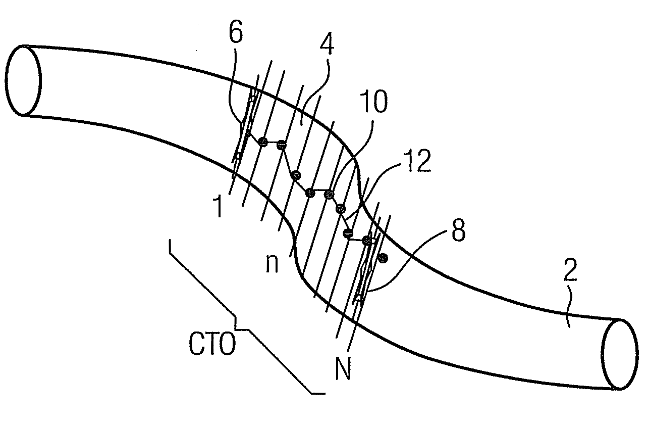
[0044]FIG. 1 shows a highly schematic view of a longitudinal section through a section of a vessel 2, here a coronary artery, which in a blockage region 4 has a total blockage (CTO=chronic total occlusion), caused by calcium and other deposits. To prepare for a catheter intervention, in which the blockage region 4 is to be broken through by the catheter tip of a catheter introduced into the vessel, a series of computer tomography sectional images of the blockage region 4 is first recorded as part of a preliminary investigation. The sectional planes of the individual sectional images—here N of them, starting with sectional plane 1 at the proximal end 6 of the blockage region 4 through to sectional plane N at the distal end 8—are so aligned that each of them shows a cross-section through the essentially cylindrical vessel 2. The vessel 2 is thus, as it were, virtually cut into numerous slices in the region of the blockage.

[0045]Such a cross-sectional image typically discloses an inner...


PUM


Abstract

The invention relates to a method for navigating a catheter with a catheter tip through a blockage region in a vessel, especially a coronary vessel, whereby the catheter is pushed forward under real-time radiological observation. The underlying objective of the invention is to arrange such a method in such a way that it permits especially simple, rapid and low risk navigation of a catheter through the blockage region in the vessel. For this purpose, in accordance with the invention a three-dimensional path through the blockage region is determined by reference to a set of sectional images or a 3D representation of the blockage region, recorded beforehand as part of a preliminary investigation, whereby a data set including the path coordinates is brought into register with the real-time radiological images, and whereby the path or a projection of the path is visualized on a display, overlaid on the real-time radiological images.A clean copy of the abstract that incorporates the above amendments is provided herewith on a separate page.

Description

CROSS REFERENCE TO RELATED APPLICATIONS[0001]The present application claims the benefit of a provisional patent application filed on Oct. 5, 2007, and assigned application No. 60 / 977,741. The present application also claims the benefit of another provisional patent application filed on Mar. 14, 2008, and assigned application No. 61 / 036,546. Both of the applications are incorporated by reference herein in their entirety.FIELD OF THE INVENTION[0002]The invention relates to a method for navigating a catheter with a catheter tip through a blockage region in a vessel, in particular a body vessel, especially a coronary vessel, whereby the catheter is pushed forward under real-time radiological observation. The invention relates in addition to an associated medical investigation and treatment device.BACKGROUND OF THE INVENTION[0003]Heart infarcts are among the conditions which most frequently result in death. In approximately 20% to 30% of all documented cases, a heart infarct occurs as a ...

Claims


Application Information

Patent Timeline
IPC IPC(8): A61B17/22A61B6/03
CPCA61B5/06A61B6/12A61B17/22A61B17/22012A61B19/50A61B19/5225A61B2019/5295A61B2017/003A61B2017/22001A61B2019/2253A61B2019/5238A61B2019/5289A61B19/5244A61B34/73A61B2090/367A61B34/20A61B2090/364A61B2090/376A61B34/10A61B90/37A61B5/062A61B5/066A61B6/032A61B6/4441A61B6/488A61B6/504
Inventor BUSCH, ERIKKLINGENBECK-REGN, KLAUSUEBLER, JOHANN
Owner SIEMENS AG
Learn More