Automated sectioning tomographic measurement system

a measurement system and automatic technology, applied in the field of tomography, can solve the problems of inability to accurately measure the depth of any particular step of material removal at small length scales, etc., and achieve the effect of accurate depth grinding

Active Publication Date: 2009-04-02
THE AEROSPACE CORPORATION
View PDF12 Cites 8 Cited by
  • Summary
  • Abstract
  • Description
  • Claims
  • Application Information

AI Technical Summary

Benefits of technology

[0011]Still another object of the invention is to provide a tomographic system for accurate sectioning an object in slices using a reporting tool aligned in depth with the object.
[0014]The invention is directed to a tomographic system and method providing controlled accurate grinding and sectioning of objects using a reporting device. The reporting device enables accurate depth grinding while concurrently providing depth information during imaging of the object. The reporting device is colocated in depth and juxtaposed in plane for precise grinding control and object imaging. Being so juxtaposed and colocated, the reporting device can provide precise depth information within images of the object. The system includes a reporting device and grinding and polishing, rinsing and washing, and imaging stations that can be integrated for providing automated acquisition of depth values of images taken at various depths in a sectioning operation. The system enables the automated collection of three-dimensional tomography datasets accumulated by mechanically de-layering grinding of objects, for which the system provides a means of straightforward automated depth sensing. A simple edge-detection algorithm is sufficient for computer control software to recognize the reporting device reading in a given image. The reporting device can be used to stop the automated serial sectioning of objects at target depths.
[0015]In the preferred form, the reporting device comprising a planar film disposed in block having a bottom surface that is slanted so that the film is slanted in the depth dimension. The planar film is preferably a high-contrast coating sandwiched between a top and a bottom of the block. Being colocated and juxtaposed, the reporting device is ground in depth as is the object, revealing a reporting line that is a line across the planar film. As the grinding proceeds in depth, the reporting line appears in successive images to move across the block. The position of the reporting line across the block provides accurate information as to current depth of grinding of the reporting tool as well as the object being ground. Being colocated and situated juxtaposed to the object of interest, the planar film reports the progress of the grinding operation. When the reporting tool and the object are imaged together, for example, in between sectioning steps, the reporting tool can provide within the image a reference to the precise depth of the ground surface of the object.
[0016]As the object is progressively sectioned, that is ground down, the surface of the inclined reporting substance is progressively removed in a coplanar manner. A corresponding reporting line appears as a high-contrast marker in images and gives an indication corresponding to the depth of the section for enabling accurate measurement of the depth of material removed at all times during the operation. The reporting tool can be used to both control the grinding as well as reporting the ground depth. The reporting device is preferably used with an automated imaging and edge-detecting subsystem. Coupled with an automated sectioning system, the reporting devices can enable control of the rates and amounts of material removed from the object. The depth resolution of systems using the device can be as fine as 2.5 nm, two orders of magnitude greater than any other automated system commercially available. The invention covers a reporting device, which can be used to measure the depth and control grinding of every image in a series of images, including but not limited to the end point depth of the sectioning operation. These and other advantages will become more apparent from the following detailed description of the preferred embodiment.

Problems solved by technology

Imaging methods based on the transmission of a probe beam through a material can be used to generate a tilt series of data for three dimensional reconstruction, but such methods are typically insensitive to structure parameters, and are limited in the resolution that can be provided.
A major problem exists with the sectioning approach.
For the mechanical sectioning approach, however, it is very difficult to accurately measure the depth of any particular step of material removal at small length scales.
This is in part caused by the difficulty in maintaining a reference plane for an object being sectioned in a planar manner.
Mechanical measurement systems that do not rely on a reference plane on the object being measured are limited to a resolution of one micron at best, rendering the sectioning only useful for objects with detail on the scale of at least twenty microns.
The profilometry method is not practical when sectioning an object in a planar manner.
The accuracy of these removal methods is severely limited to five microns in resolution.
As such, the interferometry methods suffer from the need to have external references.
Additionally, incorporation of an interferometry system into an automated sectioning or tomography system would add significant complexity and cost.
Such automated systems and methods reduce labor but are limited in resolution accuracy while sectioning through material.
In some cases, the feature of interest will have an appearance that is characteristic enough to allow for the robotic sectioning apparatus to stop automatically, but with most objects, such is not the case.
Sectioning machines are available that are capable of accurately sectioning material, but with a precision of only five microns, which is too coarse for many applications.
This offers an improvement over the measurement of only the depth of material removed, but is limited because such compensation requires calibration runs and to generate data sets related to tool wear and material grinding rates.
Also, replacement of consumables such as the sectioning head requires recalibration.
The frequent need for recalibration severely limits the use of such sectioning machines for sectioning objects and necessitates a thorough and complicated set of calibration data retention and labeling.
Its precision is five microns, which is insufficient for tomography of objects less than 1000 microns in size.
U.S. Pat. No. 6,121,147 discloses a reporting substance for detecting a polishing depth, but suffers from two major limitations.
First, the reporting substance marks only an end point in the grinding and polishing procedure.
Second, the method describes the use of spectroscopy in detection, which leads to the use of overly complicated spectroscopy devices than are necessary for this application.
This method requires the building of a complicated reporting device as well.
Prior sectioning and tomography systems and methods suffer from complicated and limited collateral reporting and sensing devices, and used the sectioned material as a sectioning object for measurement during grinding and polishing.

Method used


Image

  • Automated sectioning tomographic measurement system
  • Automated sectioning tomographic measurement system
  • Automated sectioning tomographic measurement system

Examples


Embodiment Construction

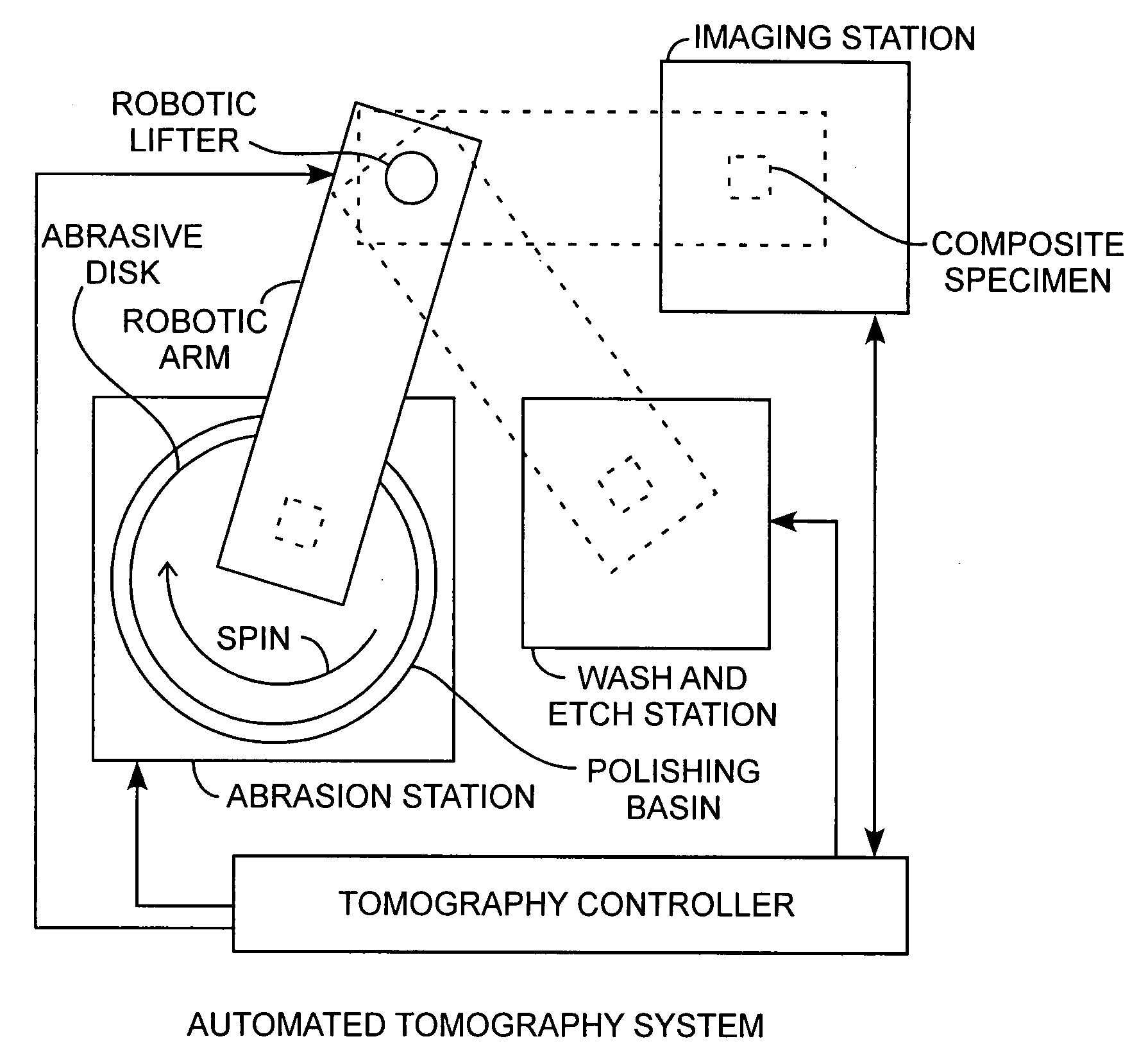
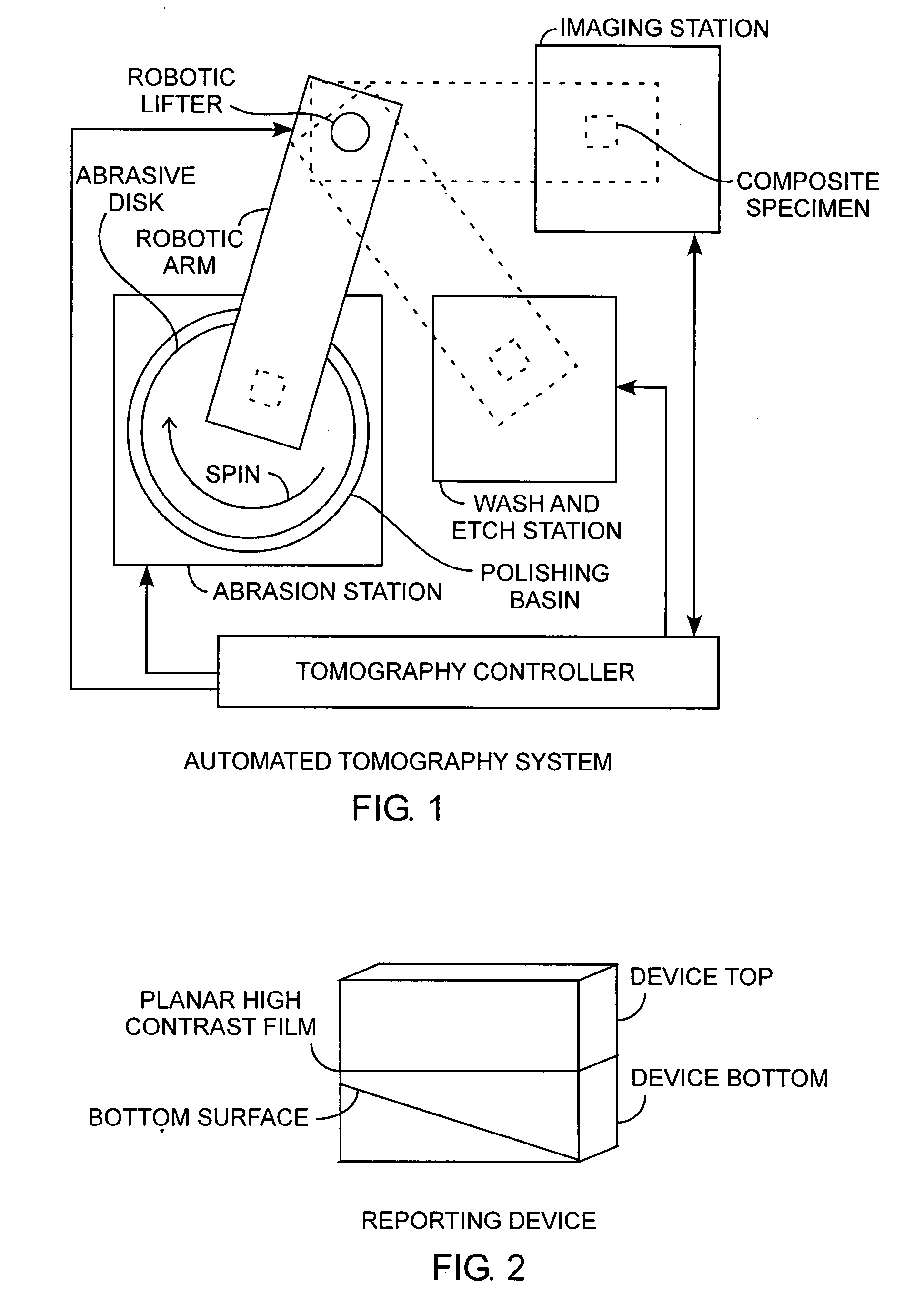
[0021]An embodiment of the invention is described with reference to the figures using reference designations as shown in the figures. Referring to FIG. 1, an automated tomography system is used for grinding a composite specimen attached to a robotic lifter. The lifter moves the composite specimen between an abrasion station for grinding the specimen, a wash and (optional) etch station for washing, cleaning, and / or drying the specimen, and an imaging station for imaging the specimen. The abrasion station would include an abrasive disk having a grinding surface. The abrasive disk can provide various levels of grinding such as coarse, medium, and fine grinding depending on the size of the abrasive grit used. The abrasive disk can be made of any of the various grinding media such as diamond, aluminum oxide, silicon carbide, or others. A supporting substrate of the abrasive disk can be made of various materials used for that purpose, such as commercially available polyester films, cloth,...


PUM


Abstract

A tomographic system includes a reporting device colocated and juxtaposed an object so that both are ground through grinding to various sectioning depths as the reporting device is ground down exposing a reporting marker along a length of the reporting device for indicating the depth of sectioning for accurate precise depth of grinding well suited for precise sectioned tomographic imaging.

Description

FIELD OF THE INVENTION[0001]The invention relates to the field of tomography. More particularly, the present invention relates to grinding, polishing, and imaging of objects in sliced sections.BACKGROUND OF THE INVENTION[0002]There is frequently a need to image the internal, three-dimensional structure of objects, in order to analyze internal structures or mechanism of failure, particularly at the scale from 200 nm to 10 mm. Imaging methods based on the transmission of a probe beam through a material can be used to generate a tilt series of data for three dimensional reconstruction, but such methods are typically insensitive to structure parameters, and are limited in the resolution that can be provided. A potentially more informative and higher spatial resolution approach to the collection of tomographic data sets can be to physically section an object in many slices while collecting images at incremental sectioning steps through the object. This sectioning approach also enables th...

Claims


Application Information

Patent Timeline
Patent Type & Authority Applications(United States)
IPC IPC(8): B24B49/12B24B7/00
CPCB24B49/12G01N2001/2866G01N1/286
Inventor ZURBUCHEN, MARK A.
Owner THE AEROSPACE CORPORATION
Why Eureka
Try Eureka