
Removal of particulates from the exhaust gas of internal combustion engines operated with a predominantly stoichiometric air/fuel mixture

a technology of stoichiometric air/fuel mixture and particulate filter, which is applied in the direction of combustible gas purification/modification, metal/metal-oxide/metal-hydroxide catalyst, etc., can solve the problem of not meeting the requirements of catalytically activated diesel particulate filters known in the prior art, and the application of temperatures above 400° c. in the downstream exhaust gas system is often difficult, and achieves high thermal cycling stability

Active Publication Date: 2009-04-02
UMICORE AG & CO KG
View PDF8 Cites 72 Cited by
  • Summary
  • Abstract
  • Description
  • Claims
  • Application Information

AI Technical Summary

Benefits of technology

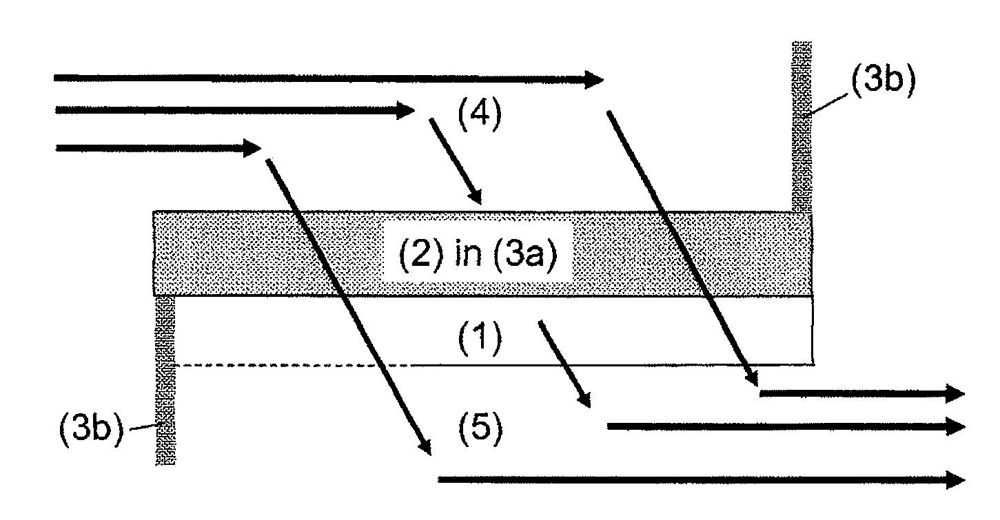
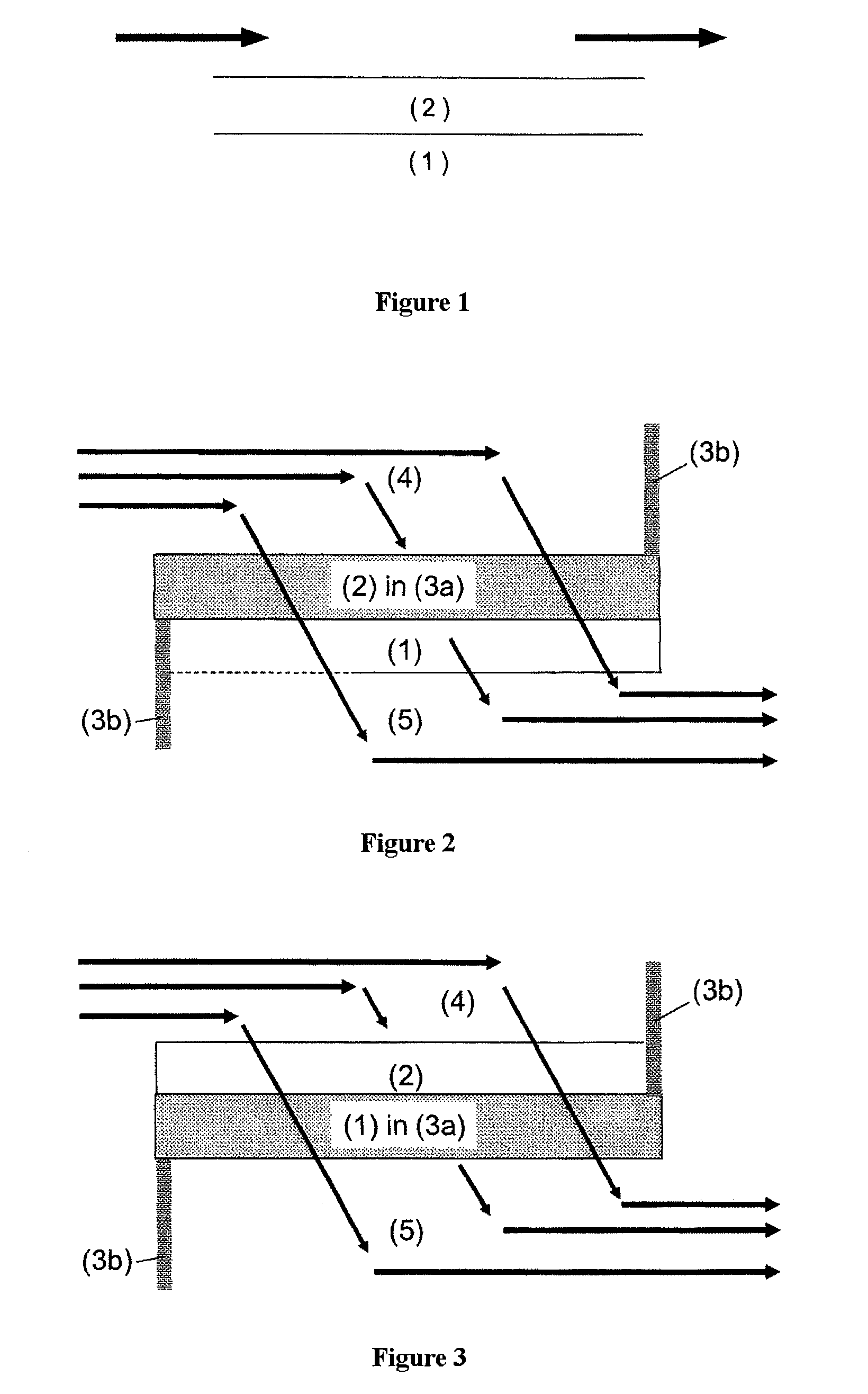
[0009]As already described, particulates in the emissions of a gasoline engine have a much smaller average particulate size. This leads to the effect that not all filter bodies known in the prior art are suitable for cleaning the exhaust gas to very substantially eliminate particulate emissions, and it is instead necessary to use substrates which are not permeable even to ultrafine particulates. Accordingly, US 2006 / 0133969 A1 describes an exhaust gas system for internal combustion engines which comprises a catalyzed ceramic wall flow filter provided with a washcoat composition which comprises an oxidation catalyst and a nitrogen oxide adsorber, wherein the uncoated ceramic wall flow filter has a porosity of >40% and an average pore size of 8-25 μm, and the washcoat composition has a D50 less than / equal to 8 μm. The washcoat composition comprises platinum and / or palladium as an active component in terms of oxidation catalysis, and a metal selected from the group of the alkali metals, the alkaline earth metals and the rare earth metals or mixtures thereof as the nitrogen oxide adsorber. In one embodiment, rhodium is applied to the outlet channels of the filter. The catalytically activated filter described in US 2006 / 0133969 is an “NOx particulate trap” (NPT), which is suitable especially for removing particulates and nitrogen oxides from the exhaust gas of predominantly lean burn diesel and gasoline engines and should be operated cyclically with cycles of rich and lean exhaust gas.
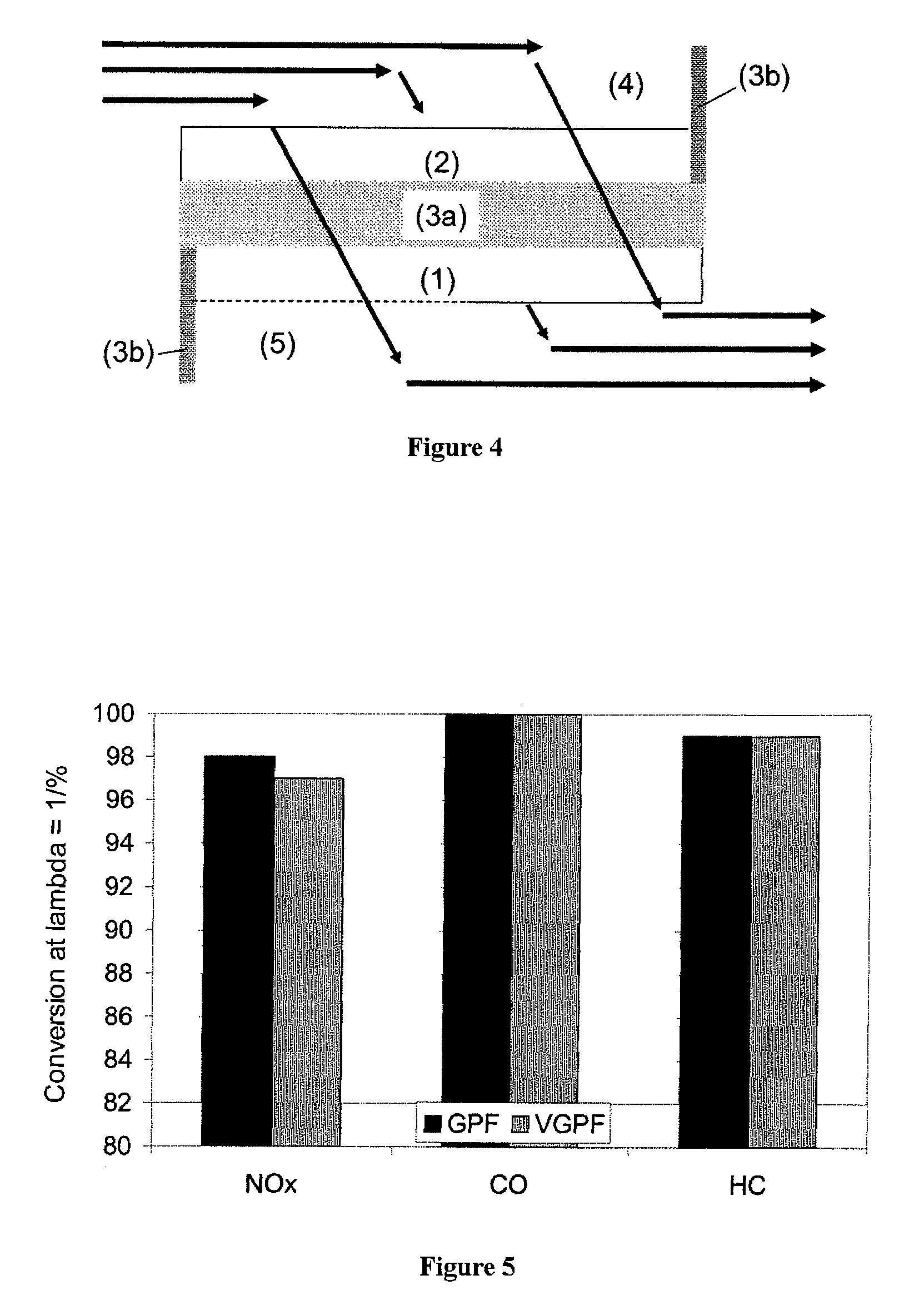
[0012]It is an object of the present invention to provide a catalytically active particulate filter which removes particulates and the gaseous hydrocarbon (HC), carbon monoxide (CO) and nitrogen oxide (NOx) pollutants from the exhaust gas of predominantly stoichiometrically operated internal combustion engines and has sufficient thermal aging stability at temperatures up to 1100° C. and high thermal cycling stability. It is a further object of the present invention to provide an apparatus and a process for removing particulates, hydrocarbons (HC), carbon monoxide (CO) and nitrogen oxides (NOx), which allows the exhaust gases of predominantly stoichiometrically operated internal combustion engines to be cleaned in such a way as to comply with future legal exhaust gas standards.

Problems solved by technology

The lowering of the soot ignition temperature is of particular significance in the case of use of particulate filters to clean diesel exhaust gases, since, owing to the “cold” combustion profile in the diesel engine, the implementation of temperatures above 400° C. in the downstream exhaust gas system is frequently difficult.
This leads to the effect that not all filter bodies known in the prior art are suitable for cleaning the exhaust gas to very substantially eliminate particulate emissions, and it is instead necessary to use substrates which are not permeable even to ultrafine particulates.
The catalytically activated diesel particulate filters known from the prior art generally do not satisfy these requirements.

Method used


Image

  • Removal of particulates from the exhaust gas of internal combustion engines operated with a predominantly stoichiometric air/fuel mixture
  • Removal of particulates from the exhaust gas of internal combustion engines operated with a predominantly stoichiometric air/fuel mixture
  • Removal of particulates from the exhaust gas of internal combustion engines operated with a predominantly stoichiometric air/fuel mixture

Examples


example

[0069]Manufacture of the First Layer:

[0070]Alumina (specific surface area 140 m2 / g) stabilized with 3% by weight of lanthanum oxide and a cerium / zirconium mixed oxide with a cerium oxide content of 40% by weight was activated according to U.S. Pat. No. 6,103,660 using barium hydroxide as a base together with palladium originating from palladium nitrate. The resulting suspension was used directly to coat the wall flow filter substrate. The suspension was applied only in the inflow channels of the filter body. After the coating, the filter was dried and calcined. The finished first layer contained the following amounts of coating:

10g / lof lanthanum-stabilized alumina10g / lof cerium / zirconium mixed oxide with 40% byweight of cerium oxide1g / lof barium oxide1.236g / lof palladium (on all components)

[0071]Manufacture of the Second Layer:

[0072]A cerium / zirconium mixed oxide with a cerium oxide content of 20% by weight was suspended in water. Thereafter, an aqueous solution of rhodium nitrate w...


PUM

PropertyMeasurementUnit
Temperatureaaaaaaaaaa
Densityaaaaaaaaaa

Abstract

The exhaust gas of internal combustion engines operated with a predominantly stoichiometric air / fuel mixture contains, as well as the gaseous hydrocarbon (HC), carbon monoxide (CO) and nitrogen oxide (NOx) pollutants, also ultrafine particulates. The introduction of the EU-5 exhaust gas standard in Europe in 2010 will for the first time impose a legal limit to these particulate emissions for gasoline vehicles. Future exhaust gas cleaning concepts for these vehicles must include devices for removing these particulates.A catalytically active particulate filter, an exhaust gas cleaning system and a process for cleaning the exhaust gases of predominantly stoichiometrically operated internal combustion engines are presented, which are suitable, as well as the gaseous CO, HC and NOx pollutants, also for removing particulates from the exhaust gas. The particulate filter comprises a filter body and a catalytically active coating consisting of two layers. Both layers contain alumina. The first layer contains palladium. The second layer contains rhodium. The latter is disposed above the first layer.

Description

[0001]The invention relates to a catalytically active particulate filter which is suitable especially for the removal of particulates from the exhaust gas of internal combustion engines operated predominantly with a stoichiometric air / fuel mixture, to a process for removing particulates, carbon monoxide, hydrocarbons and nitrogen oxides from the exhaust gas of internal combustion engines operated with a predominantly stoichiometric air / fuel mixture, and a device suitable for this purpose.[0002]Exhaust gases from internal combustion engines operated with a predominantly stoichiometric air / fuel mixture are cleaned in conventional methods with the aid of three-way catalytic converters. These are capable of converting the three essentially gaseous pollutants of the engine, specifically hydrocarbons, carbon monoxide and nitrogen oxides, simultaneously to harmless components. Apart from the gaseous hydrocarbon (HC), carbon monoxide (CO) and nitrogen oxide (NOx) pollutants, the exhaust gas...

Claims


Application Information

Patent Timeline
IPC IPC(8): B01D53/94F01N3/035B01J23/10
CPCB01D53/944Y02T10/22B01D2255/1023B01D2255/1025B01D2255/407B01D2255/9022B01D2255/908B01D2258/014B01J23/002B01J23/63B01J35/023B01J35/04B01J37/0244B01J2523/00F01N3/035F01N2510/06B01D53/945B01J2523/25B01J2523/31B01J2523/3706B01J2523/3712B01J2523/48B01J2523/824B01J2523/822Y02A50/20Y02T10/12B01J35/40B01J35/56
Inventor KLINGMANN, RAOULROESCH, MARTINLINDNER, DIETER
Owner UMICORE AG & CO KG
Learn More