Foil gas bearing supported high temperature centrifugal blower and method for cooling thereof

Inactive Publication Date: 2009-04-02
R & D DYNAMICS
View PDF40 Cites 29 Cited by
  • Summary
  • Abstract
  • Description
  • Claims
  • Application Information

AI Technical Summary

Benefits of technology

[0009]In one aspect of the present invention, a high temperature, motor driven, foil gas bearing supported blower is provided. The blower comprises a blower hot side including a volute with a process gas inlet and a process gas outlet, a diffuser attached to the volute for directing the flow of the process gas through the volute, and an impeller mounted for rotation about a central longitudinal axis within the volute for processing the gas as it flows through the volute. The blower also comprises a blower cold side including a sealed motor housing defining an interior cavity, a rotating assembly disposed within the interior cavity of the motor housing, and a motor stator assembly mounted within the motor housing. The rotating assembly comprises a rotating shaft mounted for rotation about the central longitudinal axis and a motor rotor mounted on the rotating assembly for rotation therewith, wherein the impeller is mounted at an end of the rotating assembly for rotation therewith. The blower further comprises a thermal barrier positioned between the blower hot side and the blower cold side for reducing heat transfer from the blower hot side to the blower cold side.
[0010]The blower design of the present invention may utilize an innovative thermal choke plate assembly to define a thermal barrier separating the blower into a hot side and a cold side. Preferably, the thermal choke plate assembly provides a significant temperature gradient across the hot and cold sides of the blower.
[0011]In one aspect of a preferable thermal choke plate assembly, an outer choke plate is provided adjacent to the hot side of the blower and an inner choke plate is provided adjacent to the cold side of the blower. The outer and inner choke plates are connected to one another at a neck portion transition along the inner diameter of each respective choke plate. Additionally, spacers may be provided between the choke plates to add rigidity and stiffness, as well as to aid in the dissipation of heat between the choke plates.

Problems solved by technology

Turbomachines are high technology machines that typically involve high engineering, production and assembly costs in order to achieve and maintain desired levels of performance and efficiency with reduced repair and safety concerns.
Such high costs are typically due to complex design issues, lengthy assembly procedures, and detailed maintenance requirements, all greatly influenced by the operational requirements for the machinery.
This prior art design, while good for a simple bulky application, lacks sufficient design features required to operate in an environment where the process gases are volatile or hazardous to the environment.
These machines are also often very large in size due to low operational rotating speeds, and as so sized, are usually insufficient for installation many high temperature applications.
Moreover, such blowers are often too big for many modern applications and the size cannot be reduced without compromising operation, efficiency, and safety, especially when used in high temperature applications.
The blower also has low efficiency and uses ball bearings that require regular service intervals and can also cause contamination to the process through leaking seals.
The use of such motor-driven machines—where process gas has been transported by various designs using oil lubricated ball bearings—are typically unreliable at high temperatures (about 1600° F.) due to oil coking and oil migration, insufficient cooling capacity, contamination, and safety hazards.
Such a design is undesirable due to high susceptibility to contamination, especially to the motor, which effects overall operation and efficiency of the blower.
Due to limited cooling capacity from such a design, the blower is highly inefficient.
Moreover, the ball bearings used inside the blower do not reduce noise levels to satisfactory levels.
Additionally, since the holes in the blower housing are critical to drawing in external air to cool the motor and the impeller in such a design, the blower cannot be hermetically sealed.
As a consequence, the process gas can easily mix with ambient air, which can be hazardous, especially at the high temperatures to which such a blower may be subjected.
In view of the foregoing, there is a need for a blower design that can operate efficiency at high temperatures, in a small, compact size, without suffering from the drawbacks common to prior art blower designs that tend to affect performance, operation and efficiency, and moreover, tend to compromise product safety.
There is need for a blower design for use at high temperatures that is hermetically sealed and thus does not allow any leaking of the process gas.

Method used


Image

  • Foil gas bearing supported high temperature centrifugal blower and method for cooling thereof
  • Foil gas bearing supported high temperature centrifugal blower and method for cooling thereof
  • Foil gas bearing supported high temperature centrifugal blower and method for cooling thereof

Examples


Embodiment Construction

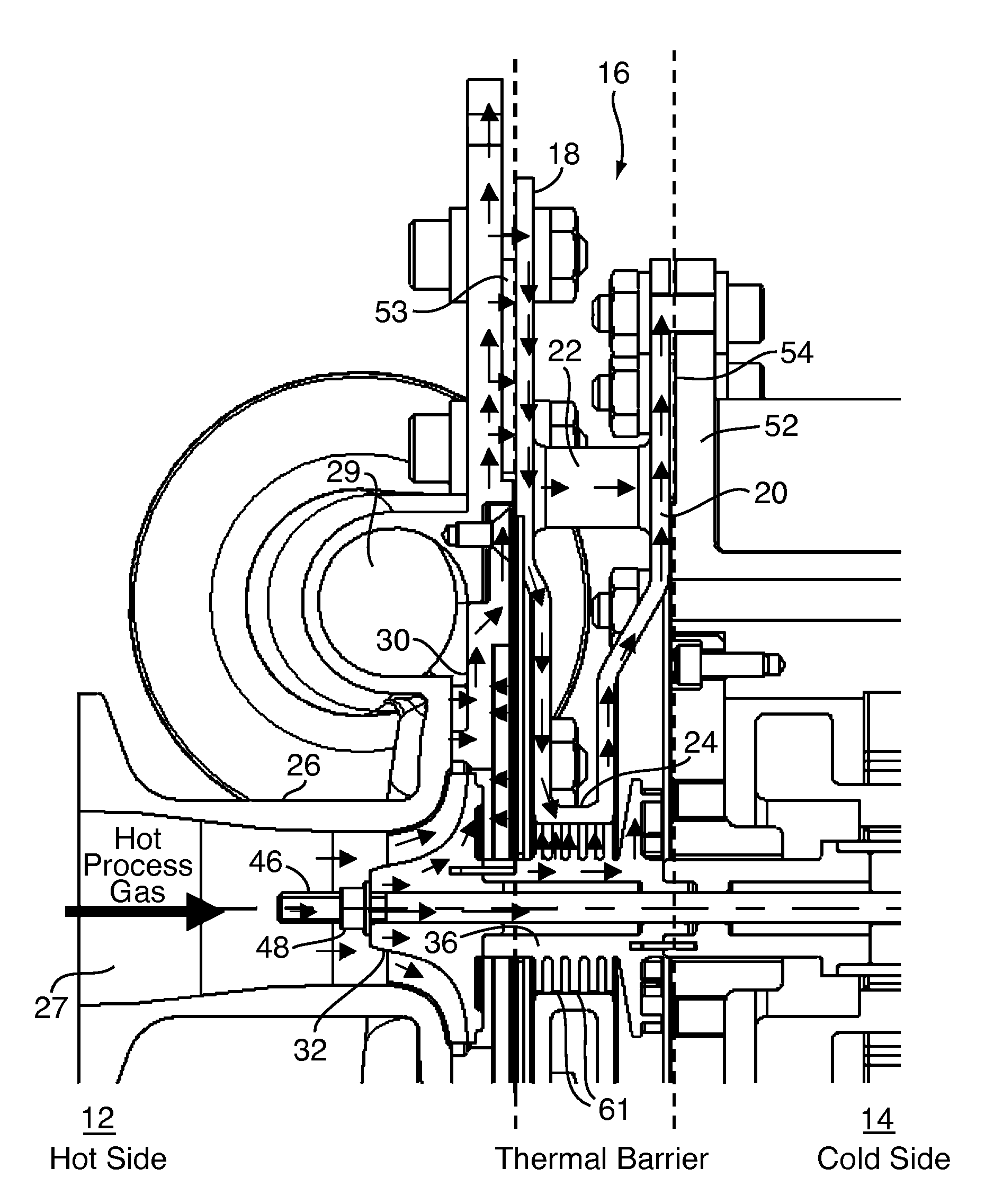
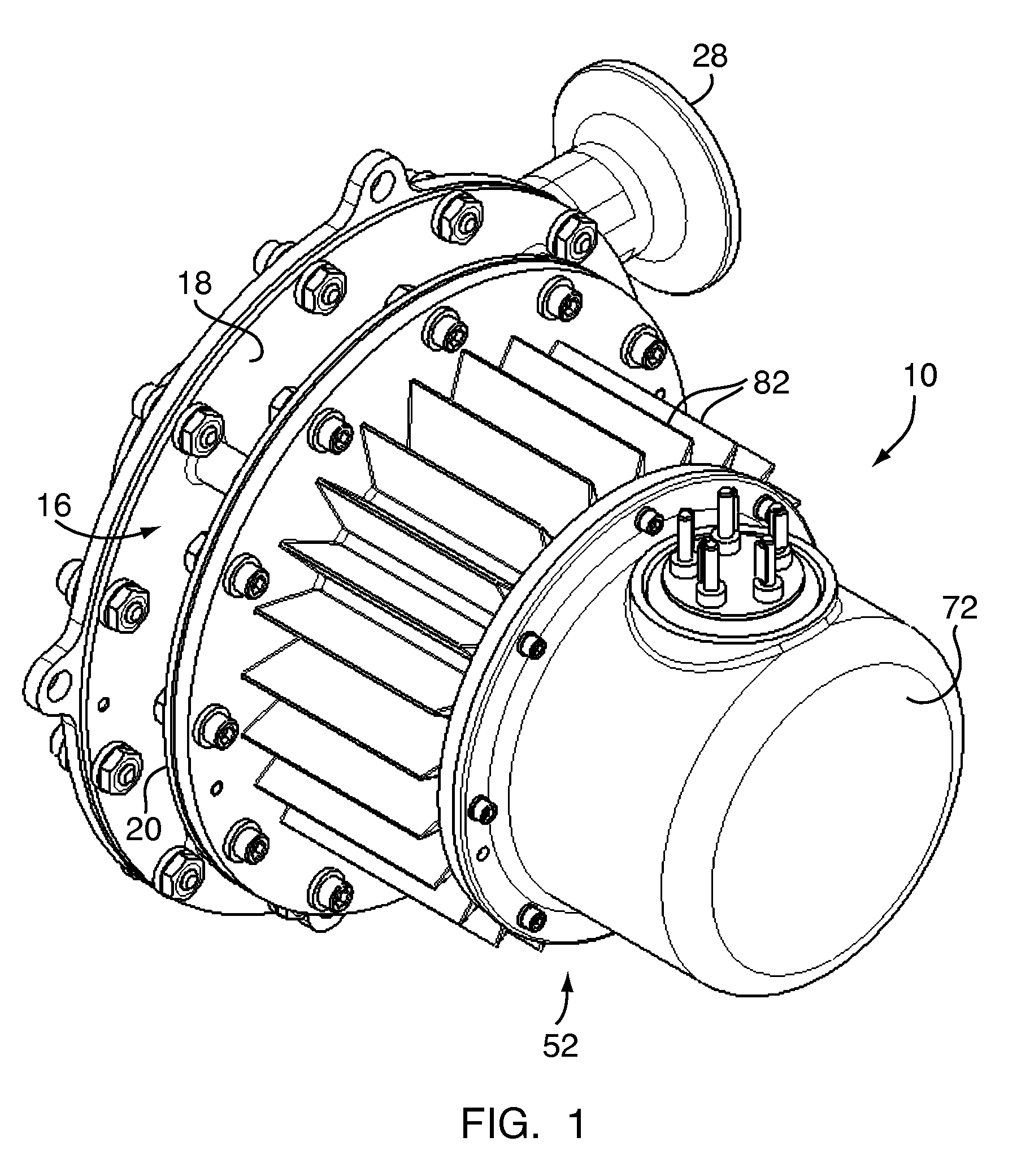
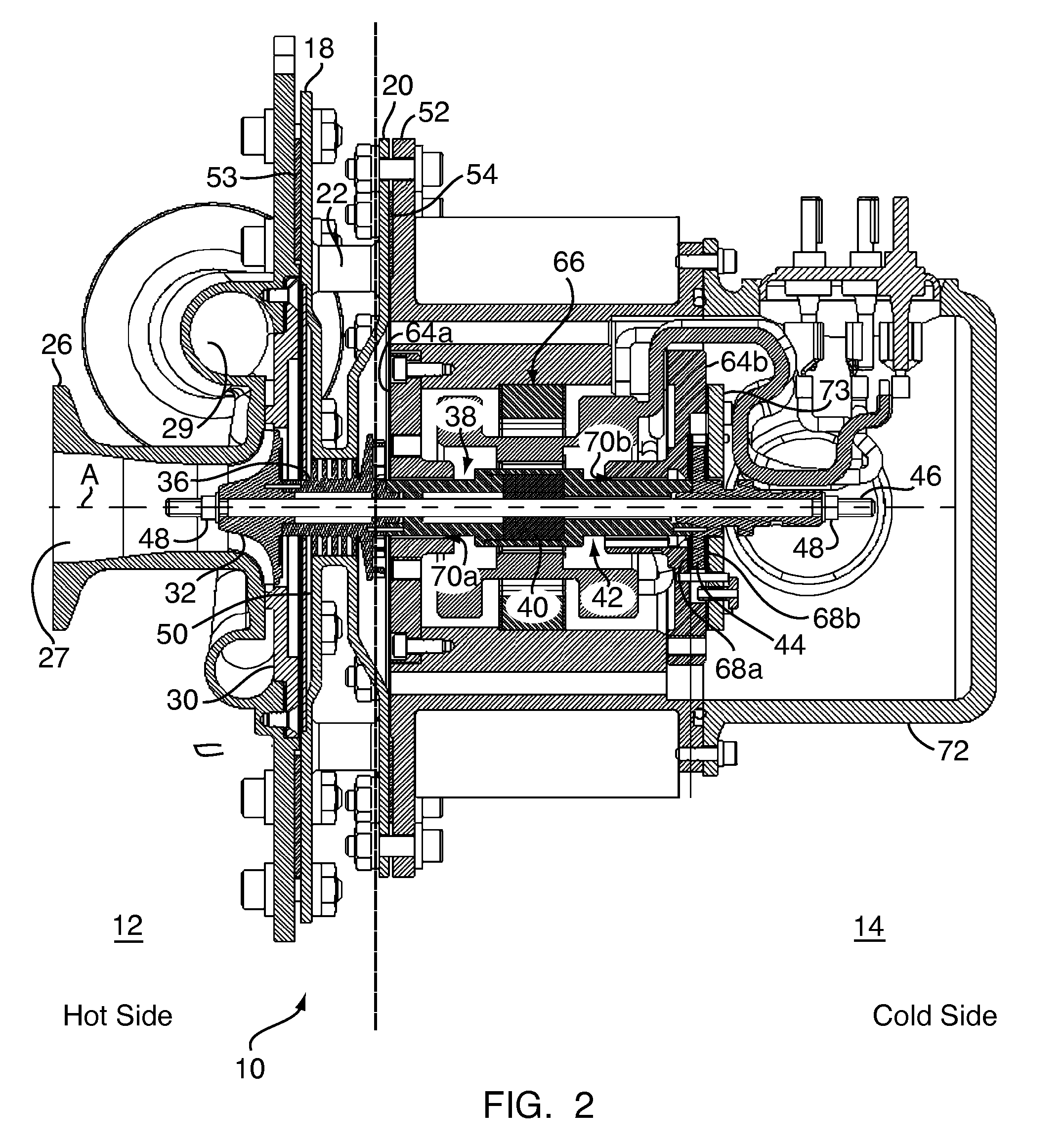
[0038]A turbomachine in accordance with the present invention is generally illustrated in FIGS. 1 and 2. As shown and described hereinafter, the illustrated turbomachine is a blower, generally designated by reference numeral 10. A perspective view of a preferable high temperature, high-speed foil gas bearing supported blower 10 incorporating the design concepts of the present invention is shown in FIG. 1. A cross-sectional view of the blower 10 in accordance with the present invention is shown in FIG. 2. More particularly, FIG. 2 illustrates separate “hot” and “cold” sides of the blower 10 and a thermal barrier formed therebetween to reduce and preferably prevent heat transfer from the “hot side” to the “cold side”, as described in more detail below. Though illustrated and described as blower 10, the present invention has application in all types of turbomachinery known to the person of ordinary skill in the art, including compressors. In general, the blower 10 of the present invent...


PUM


Abstract

This invention provides a blower design capable of high temperature operation due to use of a self-sustaining cooling scheme through a sealed motor housing in which a cooling circuit can be created, and the use of a thermal barrier across which a temperature gradient may be formed. The thermal barrier may be formed by a thermal choke plate assembly positioned between a hot side and a cold side of the blower to dissipate heat conducted from the hot side. Alternatively, the thermal barrier may be formed by an internal fan ring provided with the blower's rotating assembly to dissipate heat conducted from the blower's impeller. The thermal choke plate assembly and the fan ring may further be used in combination to block heat transfer by all modes between a hot side and a cold side of the blower.

Description

CROSS-REFERENCE TO RELATED APPLICATION [0001]This application claims the benefit of U.S. Provisional Application No. 60 / 976,971, filed Oct. 2, 2007, which is incorporated herein by reference.FIELD OF INVENTION [0002]The field of the present invention generally pertains to the conception, design and manufacture of turbomachinery, such as blowers and compressors, and associated technologies integrating such devices, and more particularly to centrifugal-type motor driven blowers and compressors capable of operating at high temperatures for use in various applications from heat treat furnaces, fuel cell systems for transportation, and other commercial uses. The present invention also generally pertains to the cooling of such turbomachinery, and more particularly to cooling centrifugal-type motor driven machines capable of operating at high temperatures as described herein.BACKGROUND OF THE INVENTION [0003]Historically, positive displacement machines and turbomachines, such as blowers an...

Claims


Application Information

Patent Timeline
IPC IPC(8): F04D29/44
CPCF04D29/584F04D29/057
Inventor AGRAWAL, GIRIDHARI L.BUCKLEY, CHARLES WILLIAMSHAKIL, ALI
Owner R & D DYNAMICS
Why Eureka
Try Eureka