[0010]Disclosed embodiments of the present invention provide a method for controlling an Adaptive Belt Load
Limiter (ABLL) for a
vehicle safety belt in a vehicle. The embodiments provide
early detection of a crash situation and a reliable
estimation of the crash
scenario such that the ABLL at an early stage is provided with the right
control signal. Hence, the disclosed embodiments provide a
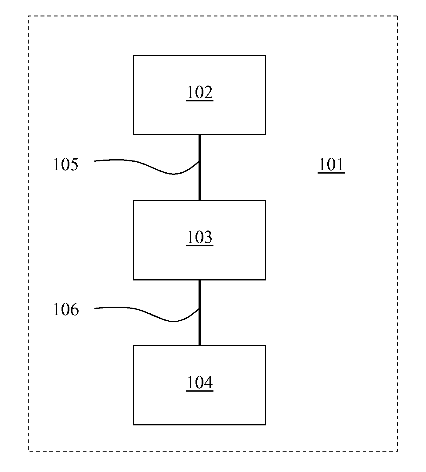
control system which, by the use of an advanced Closing Velocity Sensor (CVS) system, is able to detect an upcoming crash situation.
[0012]In some cases a control
signal may not be sent at an early stage since the desired control is to keep the ABLL at the default level and no control
signal is needed. Furthermore, there are cases, i.e. crash scenarios, when there is a desire to use other relevant sensor data (such as accelerometers or other sensors indicating the actual status of the vehicle) which may be used to verify the
crash severity estimated by the CSV. However, the CSV sensor data is very useful also in these cases since it provides additional data which make it possible to select a more appropriate control strategy for the ABLL.
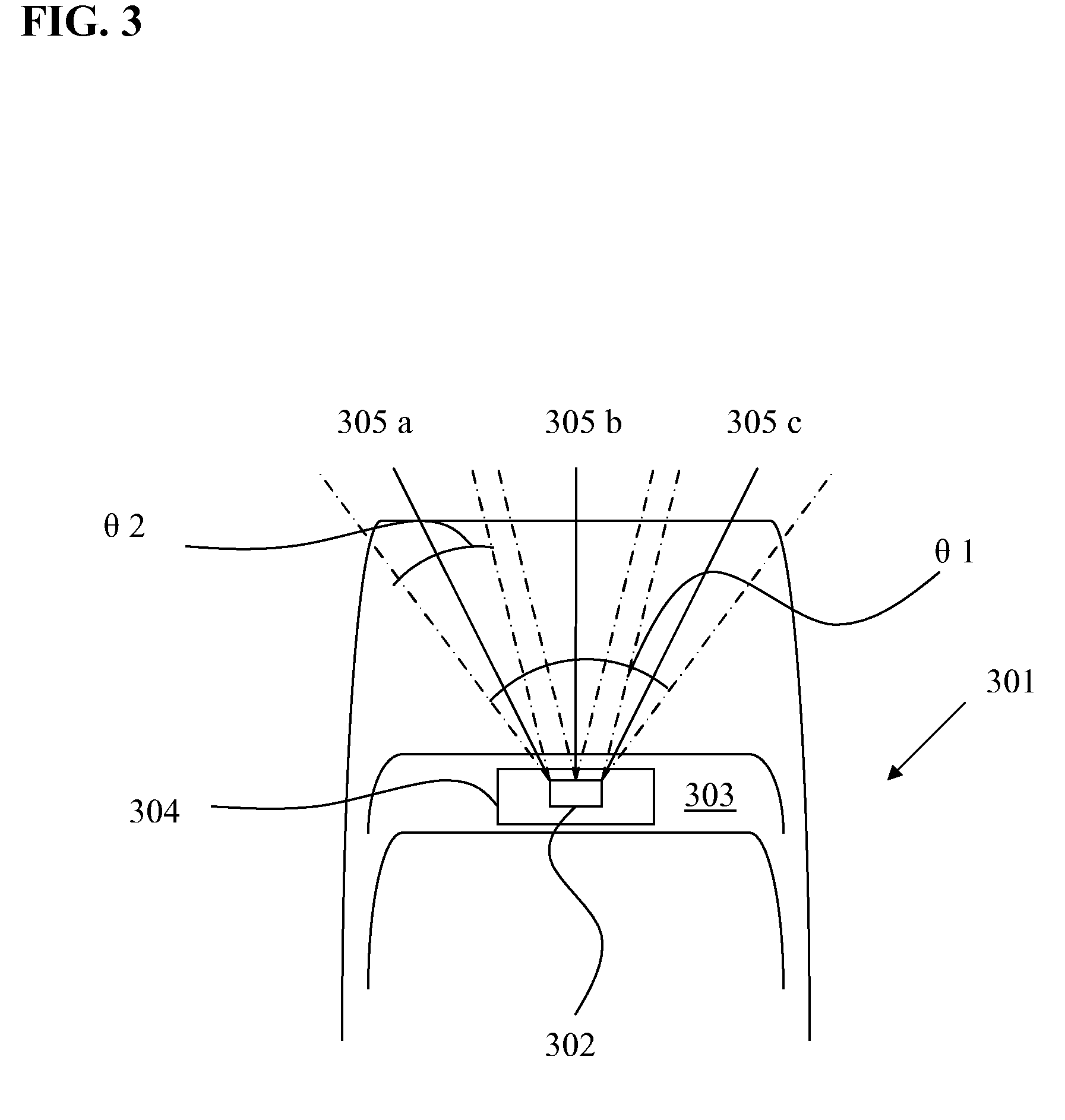
[0014]Operating at least one closing velocity sensor to detect an object in at least two different spatial areas and generate sensor signals that indicate in which of the at least two spatial areas the object is detected. By the use of CVS which are able to detect the existence of an object (or several objects) approaching the vehicles from different directions and being able to distinguish in which direction a detected object is located, it will be possible to better classify different kinds of crashes and thus use this information in deciding or classifying the severity of a probable crash situation. These area dependent CVSs are preferably mounted such that they cover at least areas
straight ahead of the vehicle's front and areas which are on the left and right side in front of the vehicle. The numbers of sensors or areas which are covered may vary as well as the size and shape of the areas which are covered. In general, the shape of the areas shall be such that the areas are mirrored with respect to a line along the longitudinal center-line of the vehicle such that the left respectively the right side in front of the vehicle are equally covered. However, in certain cases it may be desirable to use different covering of the left and right front areas, e.g. due to certain desires for the side facing the center line and thus closest to face traffic in the opposite direction (normally the left side of the vehicle as seen from the driver's position) and for the side facing the side line and thus closest to the side of the road (normally the right side). There may also be sensors covering the areas right at the sides of the vehicle if desired. The sensors may cover areas such that they do not overlap or such that they overlap to a certain part. In general, it is preferred to
mount the sensors such that they do not overlap or only have small areas overlapping in order to better distinguish in which direction an object is detected. By the use of area specific CVS it will be possible to make a more reliable classification of different kinds of crashes before the accident actually occurs and thus enable the preparation of an appropriate control
signal for a belt force limiting action in due time to control an adaptive belt load limiter to a desired level.
[0020]The prediction of an
impact or accident by a CVS as described above is particularly suitable for controlling the belt load limiter since it is important to be able to accurately determine the appropriate load level before a crash has occurred, as this permits the belt to begin to function at the same instant the crash situation starts, in contrast to an air bag
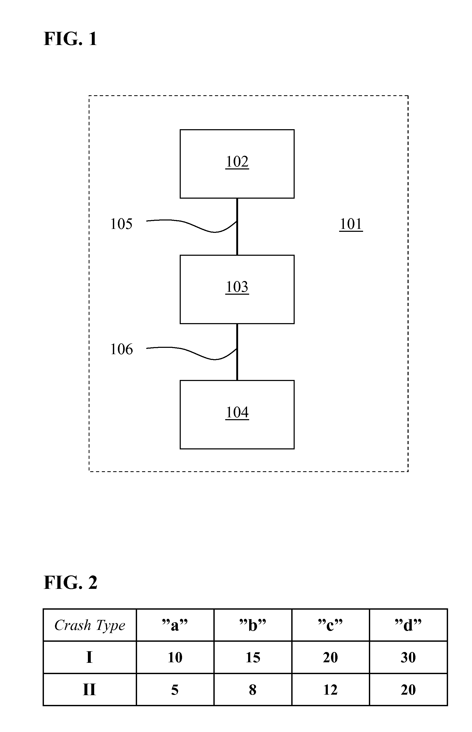
cushion which is intended to be working at a later stage in the accident. Furthermore, the ability to classify the accident by the use of area specific CVS makes it possible to better predict the estimated
impact force or the severity of the crash since there is a great difference in an front offset or angled collision compared to a full frontal
impact collision. This information may thus be used to adapt the
seat belt restraining force. By classifying different types of crashes and adapting the belt force load accordingly, it may be possible to avoid injuries to a belted occupant that may be caused by unnecessary large belt restraining forces.
[0025]According to still another embodiment of the invention, which may be used together with any of the previous embodiments described, the control signal from the RCM to the ABLL is a signal which directs a desired length of the safety belt pay out at a standard load level before the force limiter is activated. One way of deciding the belt pay out length is to measure the number of revolutions the roll has made. The control signal may also indicate a certain time period to lapse before the belt force limiter is activated but in general it is considered to be more accurate to control the length of the belt which has been paid out. This
control system is in particular designed for a
seat belt construction with an ABLL which irreversibly changes the belt force limiting action from a
standard state (i.e. where no extra belt force limitation is added) to a second state where a predefined belt force limitation is added, i.e. in the cases where it is only possible to switch between two different belt restrain forces. However, the strategy of controlling the belt pay out length as the relevant parameter for switching between different restraint force levels would work for a load limiter able to switch between several load limitation levels as well as for a load limiter which may both rise and lower the belt restrain forces.
