
Motor controller and electric power steering system

Inactive Publication Date: 2009-03-26
JTEKT CORP
View PDF7 Cites 51 Cited by
  • Summary
  • Abstract
  • Description
  • Claims
  • Application Information

AI Technical Summary

Benefits of technology

[0023]According to the above invention, the cutoff frequency of the low-pass filter is lower than the frequency of a pulse signal of a PWM signal, etc., so that time averaging the current of each phase can be performed to an extent sufficient to detect a failure of each phase.
[0024]According to the above invention, a failure of every phase in the inverter circuit and the motor can be detected, so that safe steering assisting is made possible.

Problems solved by technology

Therefore, if a failure occurs in the remaining one phase and an overcurrent flows or no current flows, the failure in the phase cannot be detected.

Method used


Image

  • Motor controller and electric power steering system
  • Motor controller and electric power steering system
  • Motor controller and electric power steering system

Examples


Embodiment Construction

1. General Configuration of Electric Power Steering System

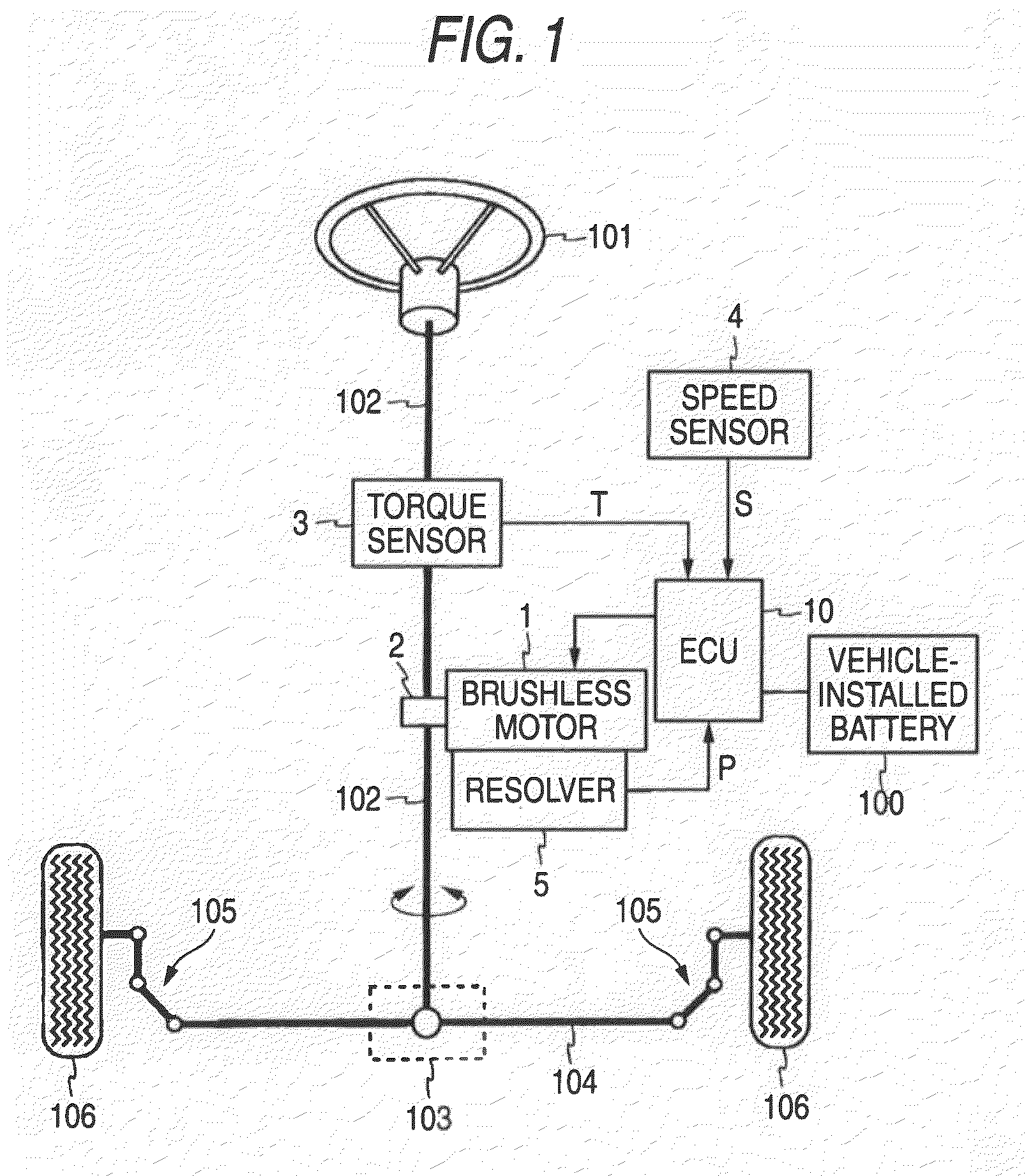
[0032]FIG. 1 is a schematic drawing to show the configuration of an electric power steering system according to an embodiment of the invention together with the configuration of a vehicle relevant to the electric power steering system. The electric power steering system shown in FIG. 1 is an electric power steering system of column assist type including a brushless motor 1, a speed reducer 2, a torque sensor 3, a speed sensor 4, a resolver 5, and an electronic control unit (ECU) 10.

[0033]As shown in FIG. 1, a steering wheel 101 is fixedly secured to one end of a steering shaft 102 and an opposite end of the steering shaft 102 is jointed to a rack shaft 104 through a rack and pinion mechanism 103. Opposite ends of the rack shaft are respectively jointed to wheels 106 through joint members 105 each made up of a tie rod and a steering knuckle arm. When a driver turns the steering wheel 101, the steering shaft 102 rotates and acc...


PUM


Abstract

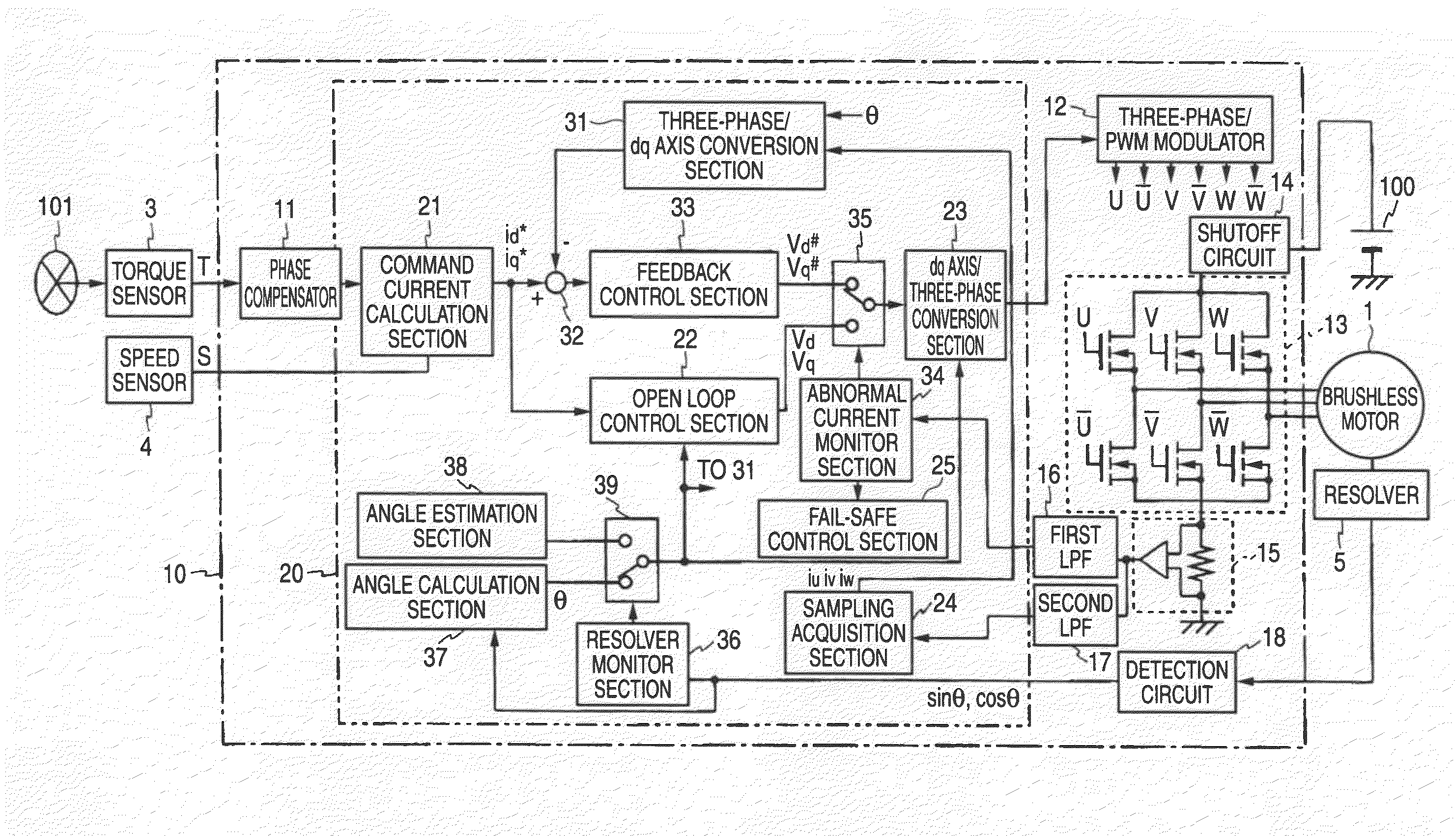
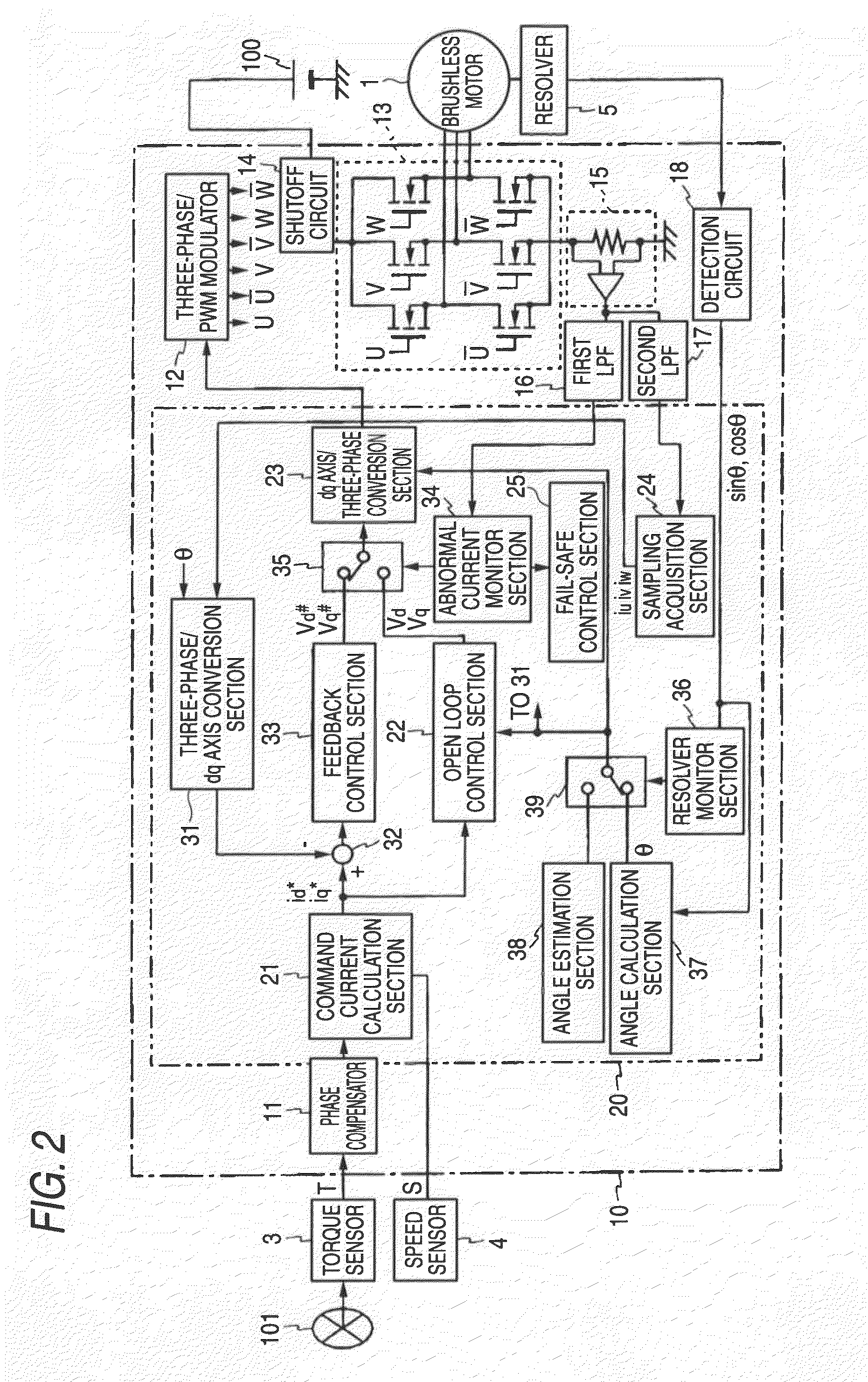
A current sensor of a motor controller detects the current applied to a motor drive circuit and thus a phase where a failure cannot be detected would occur without taking any measures. However, an abnormal current monitor section contained in a microcomputer receives a voltage signal of an average value of the currents detected in the current sensor by allowing a signal to pass through a first LPF having a cutoff frequency sufficiently lower than the frequency of a PWM signal. Therefore, whether or not the value is within a predetermined normal range is checked, whereby whether or not some failure containing a failure of the current sensor occurs can be easily determined about every phase.

Description

BACKGROUND OF THE INVENTION[0001]This invention relates to a motor controller for controlling a brushless motor and an electric power steering system including the motor controller.[0002]Generally, an electric power steering system for giving steering assist force to a steering mechanism of a vehicle by driving an electric motor in response to a steering torque added to a steering wheel by a driver has been used. A brush motor has been widely used as the electric motor of the electric power steering system; in recent years, a brushless motor has also been used from the viewpoints of improvement of reliability and durability, a decrease in inertia, and the like.[0003]Generally, to control torque generated by a motor, a motor controller detects a current flowing into the motor and performs PI control (proportional-plus-integral control) based on the difference between the current to be supplied to the motor and the detected current. A motor controller for driving a three-phase brushle...

Claims


Application Information

Patent Timeline
IPC IPC(8): H02H7/085H02P6/08B62D5/04B62D6/00B62D119/00B62D137/00H02P6/06H02P6/16H02P21/00H02P27/04
CPCH02P6/002B62D5/0487H02P6/28H02P29/027
Inventor NAGASE, SHIGEKIUEDA, TAKESHIMATSUBARA, KENOYA, TOSHIAKIYOSHII, YASUYUKI
Owner JTEKT CORP
Learn More