
Drying jig, drying method of honeycomb molded body, and manufacturing method of honeycomb structured body

a technology of honeycomb and manufacturing method, which is applied in the manufacture of cheese, drying machines, butter, etc., can solve the problems of affecting the quality of honeycomb, so as to prevent separation or opening

Inactive Publication Date: 2009-03-26
IBIDEN CO LTD
View PDF99 Cites 59 Cited by
  • Summary
  • Abstract
  • Description
  • Claims
  • Application Information

AI Technical Summary

Benefits of technology

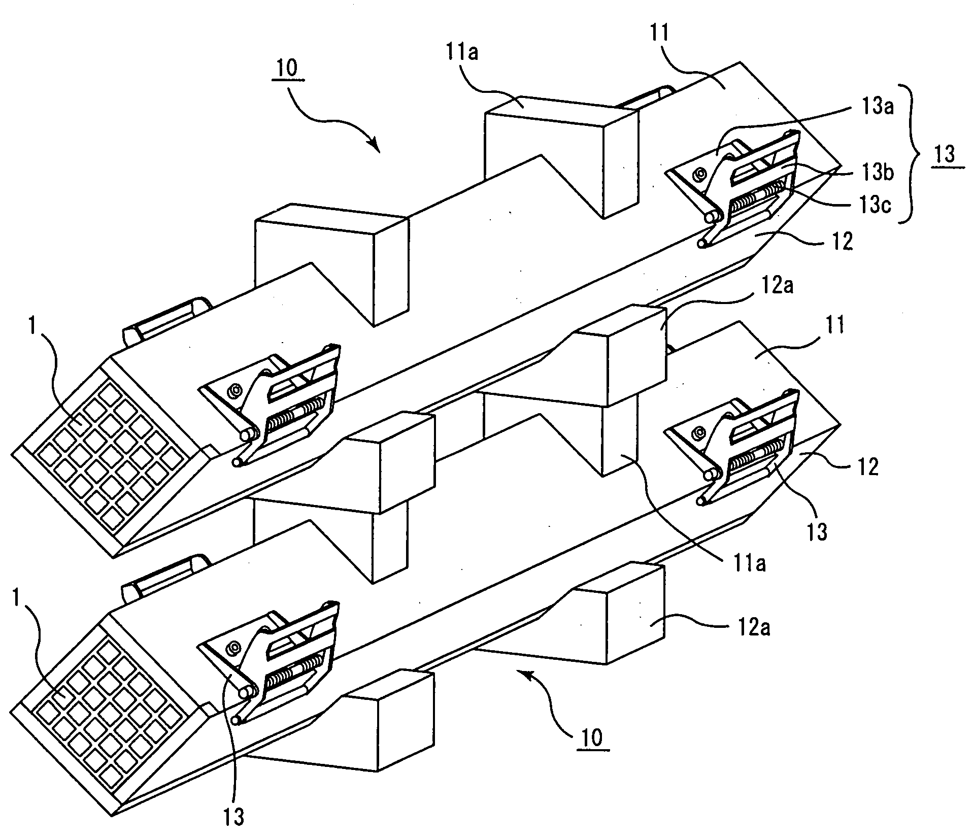
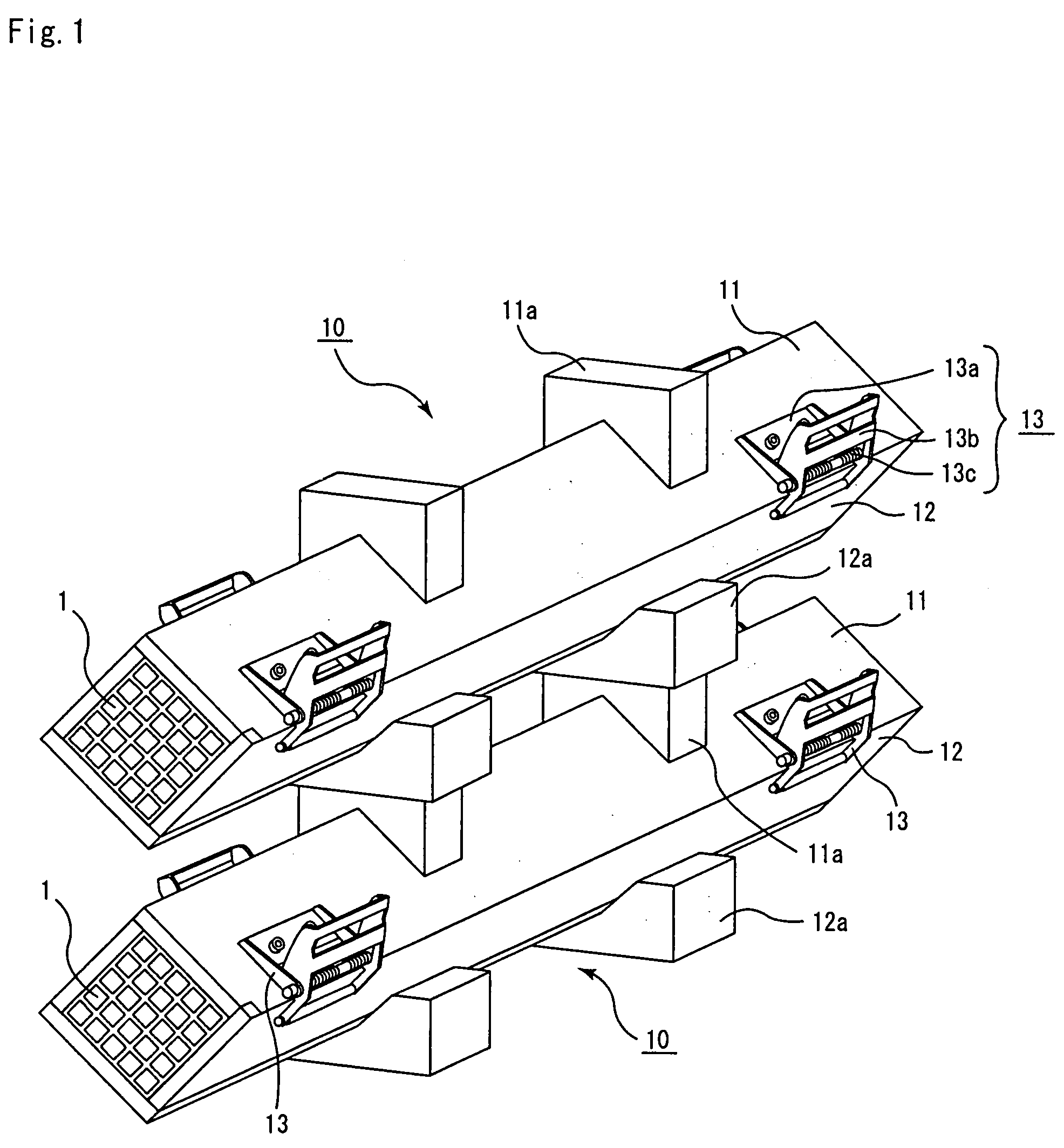
[0015]A drying jig of the present invention is a drying jig for a pillar-shaped honeycomb molded body having a large number of cells longitudinally placed in parallel with one another with a cell wall therebetween, comprising: a fixing member for preventing separation or opening of the drying jig; and a piling member which enables the drying jig to be piled up in multi stage at the time of drying.
[0024]A drying method of a honeycomb molded body of the present invention is a drying method of a honeycomb molded body comprising: drying a honeycomb molded body after surrounding, in an adhered state with a drying jig, nearly the whole surface of a side face parallel to the longitudinal direction of a pillar-shaped honeycomb molded body having a large number of cells longitudinally placed in parallel with one another with a cell wall therebetween, wherein the drying jig comprises a fixing member for preventing separation or opening of the drying jig, and a piling member which enables the drying jig to be piled up in multi stage at the time of drying, preventing separation or opening of the drying jig by adjusting the fixing member after surrounding the honeycomb molded body with the drying jig, and thereafter piling up in multi stage through the piling member, the honeycomb molded body under a surrounded state by the drying jig, passing the honeycomb molded body inside a dryer for a predetermined period of time, so that the honeycomb molded body is dried.
[0034]A manufacturing method of a honeycomb structured body of the present invention is a manufacturing method of a honeycomb structured body comprising: manufacturing a pillar-shaped honeycomb molded body having a large number of cells longitudinally placed in parallel with one another with a cell wall therebetween, by molding a ceramic material; drying the honeycomb molded body after surrounding, in an adhered state with a drying jig, nearly the whole surface of a side face parallel to the longitudinal direction of the honeycomb molded body; and firing the honeycomb molded body to manufacture a honeycomb structured body comprising a honeycomb fired body, wherein the drying jig comprises a fixing member for preventing separation or opening of the drying jig, and a piling member which enables the drying jig to be piled up in multi stage at the time of drying, and in the drying of the honeycomb molded body, after surrounding the honeycomb molded body with the drying jig, separation or opening of the drying jig is prevented by adjusting the fixing member, and the honeycomb molded body under a surrounded state by the drying jig is piled up in multi stage through the piling member thereafter, drying the honeycomb molded body by passing the honeycomb molded body inside a dryer for a predetermined period of time.

Problems solved by technology

Recently, it becomes a problem that particulates such as soot, contained in exhaust gas emitted from internal combustion engines for vehicles such as a bus, a truck and the like, construction equipment and the like, do harm to the environment or the human health.

Method used


Image

  • Drying jig, drying method of honeycomb molded body, and manufacturing method of honeycomb structured body
  • Drying jig, drying method of honeycomb molded body, and manufacturing method of honeycomb structured body
  • Drying jig, drying method of honeycomb molded body, and manufacturing method of honeycomb structured body

Examples


example 1

[0221]250 kg of α type silicon carbide powder having an average particle diameter of 10 μm, 100 kg of α type silicon carbide powder having an average particle diameter of 0.5 μm, and 20 kg of an organic binder (methyl cellulose) were mixed to prepare a mixed powder.

[0222]Next, separately, a liquid mixture was prepared by mixing 12 kg of a lubricant (UNILUB made by NOF Corp.), 5 kg of a plasticizer (glycerol) and 65 kg of water, and this liquid mixture and the mixed powder were mixed with a wet mixer to prepare a wet mixture.

[0223]Then, this wet mixture was subjected to extrusion-molding and subsequently cut to prepare a honeycomb molded body.

[0224]Next, the honeycomb molded body was dried with a dryer in which a microwave and a hot air were used in combination to reduce its water content by 40%.

[0225]Then, the honeycomb molded body, in which the water content was reduced by 40%, was held by a drying jig (made of epoxy resin) shown in FIG. 1, and was sent into a hot-air dryer having ...

example 2

[0229]A honeycomb fired body was manufactured by following the same procedure as in Example 1 except for drying the honeycomb molded body in a state of piling up the drying jig in three stages in drying treatment using a drying jig.

reference example 1

[0230]A honeycomb fired body was manufactured by following the same procedure as in Example 1 except for drying the honeycomb molded body in one stage without piling up the drying jig in drying treatment using a drying jig.


PUM

PropertyMeasurementUnit
Shapeaaaaaaaaaa

Abstract

A drying jig of the present invention is a drying jig for a pillar-shaped honeycomb molded body having a large number of cells longitudinally placed in parallel with one another with a cell wall therebetween, comprising: a fixing member for preventing separation or opening of the drying jig; and a piling member which enables the drying jig to be piled up in multi stage at the time of drying.

Description

CROSS-REFERENCE TO RELATED APPLICATIONS[0001]This application claims priority of EP 06110528.4 filed on Feb. 28, 2006. The contents of this application are incorporated herein by reference in their entirety.BACKGROUND OF THE INVENTION[0002]1. Field of the Invention[0003]The present invention relates to a drying jig, a drying method of a honeycomb molded body, and a manufacturing method of a honeycomb structured body.[0004]2. Discussion of the Background[0005]Recently, it becomes a problem that particulates such as soot, contained in exhaust gas emitted from internal combustion engines for vehicles such as a bus, a truck and the like, construction equipment and the like, do harm to the environment or the human health.[0006]In order to solve this problem, there are proposed various filters using a honeycomb structured body made of porous ceramic as a filter for collecting particulates in exhaust gas and purifying the exhaust gas.[0007]When a honeycomb structured body is manufactured b...

Claims


Application Information

Patent Timeline
IPC IPC(8): H05B6/64
CPCB28B11/243C04B38/0006F26B21/006F26B25/14F26B2210/02C04B35/565C04B2235/383C04B2235/428C04B2235/5436C04B2235/5445C04B2235/606C04B2235/96B28B11/248C04B38/067C04B38/068C04B38/08
Inventor KASAI, KENICHIRONARUSE, KAZUYA
Owner IBIDEN CO LTD
Learn More