
System And Method For Accessing And Using A Supercomputer

a supercomputer and supercomputer technology, applied in the field of methods for can solve the problems of not providing significant user interactivity in the current method of accessing and using clusters of supercomputers, not giving any control over the execution of jobs, and not providing significant user interactivity

Active Publication Date: 2009-03-19
MASSIVELY PARALLEL TECH
View PDF28 Cites 17 Cited by
  • Summary
  • Abstract
  • Description
  • Claims
  • Application Information

AI Technical Summary

Benefits of technology

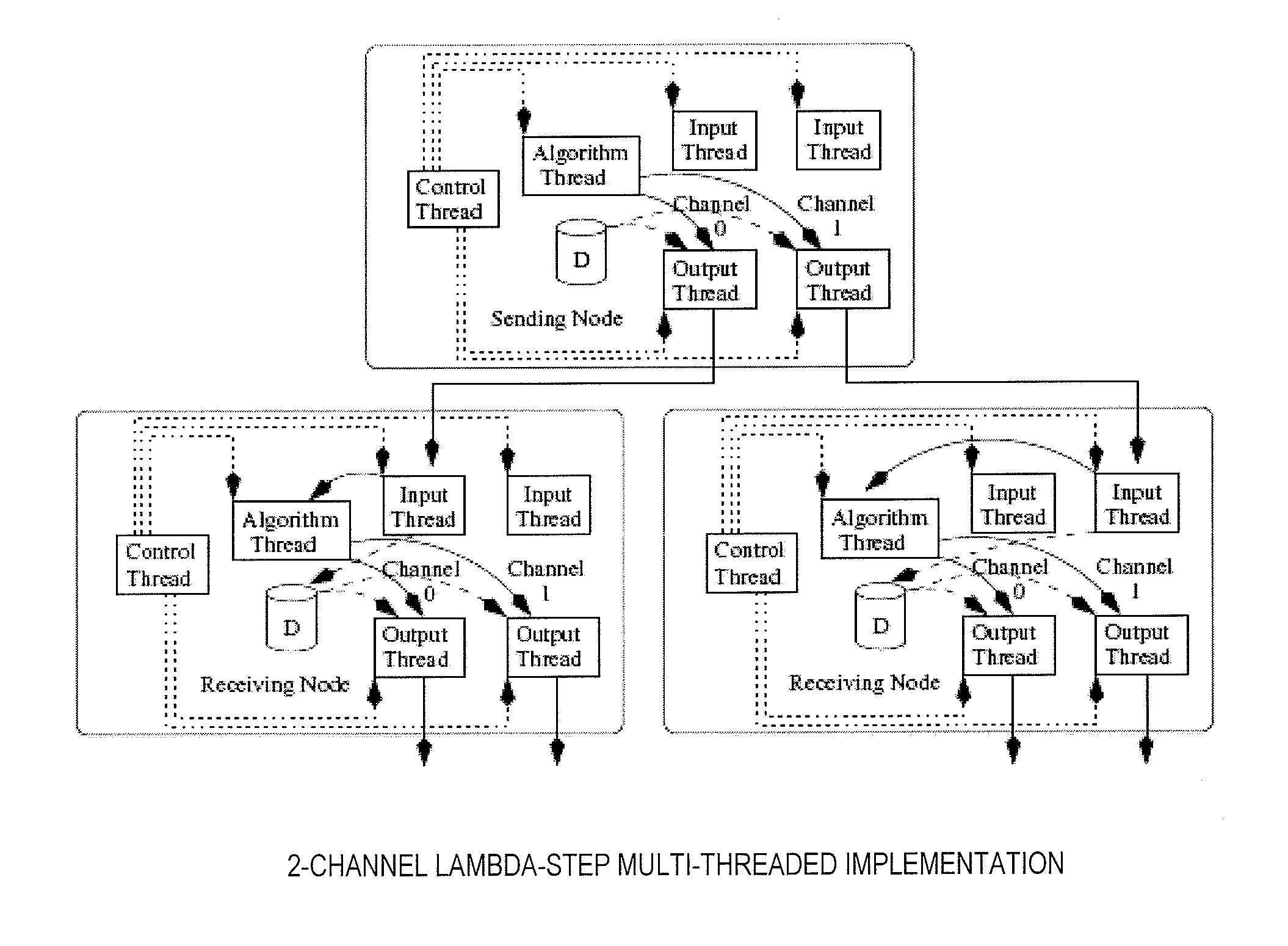
[0011] In another embodiment, a parallel processing system with overlapped communication includes a plurality of processing nodes, each having an input communication channel and an output communication channel. Each input communication channel has an associated input thread and each output communication channel has an associated output thread. The input and output threads operate to concurrently receive and transmit data on the input and output communication channels and cooperate, when the received data is to be sent to another processing node, to transmit data received via the input communication channel on the output communication channel with a delay T′. At least one switch connects to the input and output communication channels of each of the processing nodes, and is configurable to transfer data from the output channel of a first of the processing nodes to the input channel of a second of the processing nodes. The at least one switch is configured upon setup of the parallel processing system to provide communication between the processing nodes based upon a topology of the parallel processing system, such that the parallel processing system broadcasts data to each processing node with a minimum delay.

Problems solved by technology

Current methods for accessing and using cluster of supercomputers do not provide any significant level of user interactivity.
Since the user does not have direct control over job execution, this method does not lend itself to interactive computing.
More specifically, the user is typically not granted any control over execution of the job and therefore cannot follow its progress easily or identify and / or correct processing anomalies.
Further, typical supercomputer technology does not provide functionality or flexibility to allow implementation of such control and interaction.
Communication between nodes of a parallel processing environment forms a significant cost when using the parallel processing environment to process jobs.
These communication costs effectively limit the number of usable nodes within the parallel processing environment.
A further limitation of parallel processing environments is the configuration of individual nodes within the environment.
Where the nodes are statically defined and configured by some external source, such configuration is time consuming and error prone.
Further, where a particular device fails, such as the system configuration controller, the entire parallel processing environment becomes unusable.

Method used


Image

  • System And Method For Accessing And Using A Supercomputer
  • System And Method For Accessing And Using A Supercomputer
  • System And Method For Accessing And Using A Supercomputer

Examples


example 1

1 Transmission Node

[0297]FIG. 42 shows a network of nodes in an initial state 2020, where only one copy of the code is stored on a node 2022 within the network. The transmission may be better served using a broadcast mechanism. Node 2022 contains the code and the locations of all other nodes in the network. Other nodes 2024, 2026, 2028 and 2030 do not contain the code.

[0298]FIG. 43 shows the state of the network of FIG. 42 after one time unit 2040. Node 2022 has the code and is in the CT-transmit state after the first time unit; node 2022 transmits 2042 the code to node 2024.

[0299] In the second time unit 2060, shown in FIG. 44, an association is formed with node 2024 and node 2026 is placed into I-inactive state. A node in the I-inactive state that is contacted by a node in the CT-Transmit state will compare its association size. The third time unit 2080 is shown in FIG. 45 and the fourth time unit 2100 is shown in FIG. 46.

[0300] By time fifth unit 2120 as shown in FIG. 47, nod...

example 2

2 Transmission Nodes

[0301] This example shows how these rules allow multiple transmission nodes to select the transmission node that should become the AA-List node.

[0302]FIG. 49 shows one exemplary network at a first time unit 2200 with two nodes 2202 and 2204 containing the code and the same list of available nodes in the network. The available node lists in nodes 2202 and 2204 each includes nodes 2206, 2208 and 2210 and the other transmission nodes 2204 and 2202, respectively. Since the transmission nodes randomize their node lists they can start acquiring their associations. A second time unit 2220 is shown in FIG. 50, where node 2202 acquires 2222 node 2206 and node 2204 acquires 2224 node 2208. FIG. 51 shows a third time unit 2240 where node 2202 acquires node 2210 and node 2204 attempts to acquire node 2206. Since node 2206 is already in an association, the association size is compared and nodes 2204 and 2208 join the association of node 2202, as shown in the fourth time uni...

example 3

Homogeneous 1-Channel Agents, 1 Home Node Goal

[0316] For the first example, the environment is set to produce a large number of C nodes and one H node. FIG. 55 shows one exemplary environment at a first time unit 2400 and having ten undifferentiated homogeneous nodes, each with a single communication channel, labeled 0 through 9, and an AA list node 2402. The initial state of each of these nodes is given in Table 3. Example 3, Initial States. The maximum association size is set to seven and the system quiescence wait time is set to three.

TABLE 3Example 3, Initial StatesNode #State0I-active1I-active2I-active3I-active4I-active5I-active6I-active7I-active8I-active9I-active

[0317] The number of nodes that can access the AA List is limited to one. FIG. 56 shows the environment of FIG. 55 at a second time unit 2240, where node 4 is the first to access 2442, 2444, AA list node 2402. It then transitions to T-init state, as shown in Table 4. Example 3, Time Unit 2 States.

TABLE 4Example 3,...


PUM


Abstract

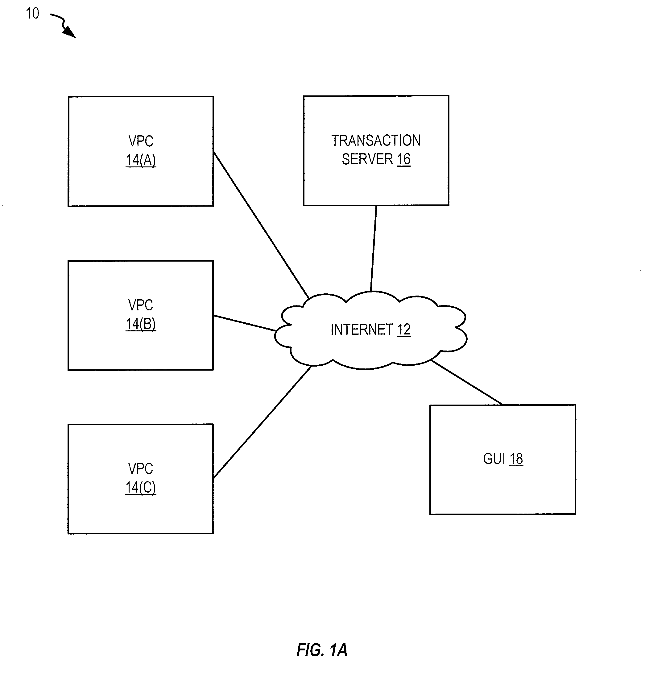
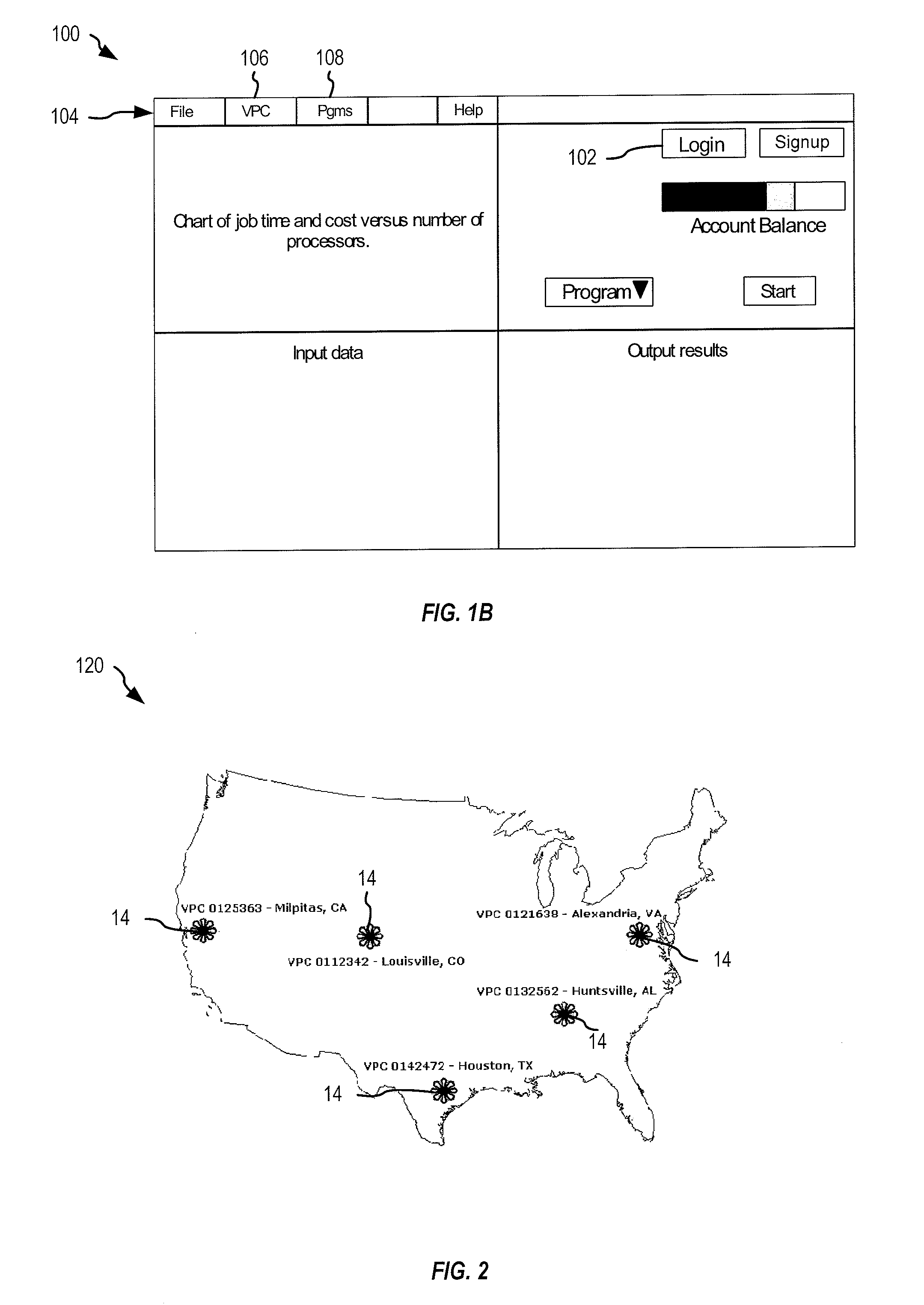
Systems and methods form and control a supercomputer based upon a parallel processing architecture such as a Howard cascade. A graphical user interface allows a user to interact with one or more virtual power centers of the supercomputer facility. A plurality of processing nodes self-organize into one or more virtual power centers. The processing nodes utilize overlapped input and output for improved communication.

Description

RELATED APPLICATIONS [0001] This application claims priority to U.S. Provisional Application No. 60 / 841,928, filed Sep. 1, 2006, incorporated herein by reference.BACKGROUND [0002] Current methods for accessing and using cluster of supercomputers do not provide any significant level of user interactivity. Typically, a user submits a job to a system queue serviced by a job control subsystem. The job is then scheduled for batch execution based on criteria established by the administrators of the supercomputer. Although users are totally dependent on these criteria, they are not presented to them in a way that allows the user to easily determine when their job will start and finish. Since the user does not have direct control over job execution, this method does not lend itself to interactive computing. [0003] More specifically, the user is typically not granted any control over execution of the job and therefore cannot follow its progress easily or identify and / or correct processing an...

Claims


Application Information

Patent Timeline
Patent Type & Authority Applications(United States)
IPC IPC(8): G06F9/30G06F15/80G06F3/048G06F9/50G06F9/02
CPCG06F9/5072
Inventor HOWARD, KEVIN D.LUPO, JAMES A.GESKE, THOMASROBERTSON, NICK
Owner MASSIVELY PARALLEL TECH
Learn More