Eureka AIR delivers breakthrough ideas for toughest innovation challenges, trusted by R&D personnel around the world.

Exposure apparatus and exposure method

Inactive Publication Date: 2009-03-19
NIKON CORP
View PDF7 Cites 27 Cited by
  • Summary
  • Abstract
  • Description
  • Claims
  • Application Information

AI Technical Summary

Benefits of technology

[0018]According to the first or second aspects, the first object such as a mask does not move with respect to the illuminating beam, but the illuminating beam is moved to scan the first object in the prescribed scanning direction, and is guided onto the area to be exposed on the second object. Therefore, the first object need not be driven. Accordingly, a drive apparatus having a large movement stroke need not be installed, thereby enabling a reduction in the weight of the stage.
[0021]According to the third or fourth aspects, since the first object such as a mask does not move with respect to the illuminating beam, but the illuminating beam is moved to scan the first object in the prescribed scanning direction, the stage device need not be driven with a large stroke. Accordingly, a drive apparatus having a large movement stroke need not be installed, thereby enabling a reduction in the weight of the stage.
[0024]According to the fifth or sixth aspects, since the first object such as a mask does not move with respect to the illuminating beam, but the illuminating beam is moved to scan the first object in the prescribed scanning direction, and is guided onto the area to be exposed on the second object, the stage device need not be driven with a large stroke. Accordingly, a drive apparatus having a large movement stroke need not be installed, thereby enabling a reduction in the weight of the stage.
[0026]According to the aspects of the present invention, the apparatus can be made small and light, and can improve the exposure accuracy, without causing a considerable cost increase.

Problems solved by technology

Therefore, it has not been easy to improve both the exposure accuracy and the throughput in the scanning stepper.
Therefore, the reticle has large dimensions, thereby increasing the cost required for production of the reticle.
Moreover, since a large-dimension reticle is used, the size of the reticle stage increases, thereby causing a problem of cost increase of the exposure apparatus.
Therefore, a stator of a linear motor for driving the reticle stage becomes large, increasing the weight of the reticle stage or increasing the heat output involved with driving of the stage, thereby causing a problem in that factors that decrease positioning accuracy such as air fluctuations increase.
Therefore, there are problems in that the cost of the exposure apparatus considerably increases, and the cost for manufacturing the reticles is doubled.

Method used


Image

  • Exposure apparatus and exposure method
  • Exposure apparatus and exposure method
  • Exposure apparatus and exposure method

Examples


first embodiment

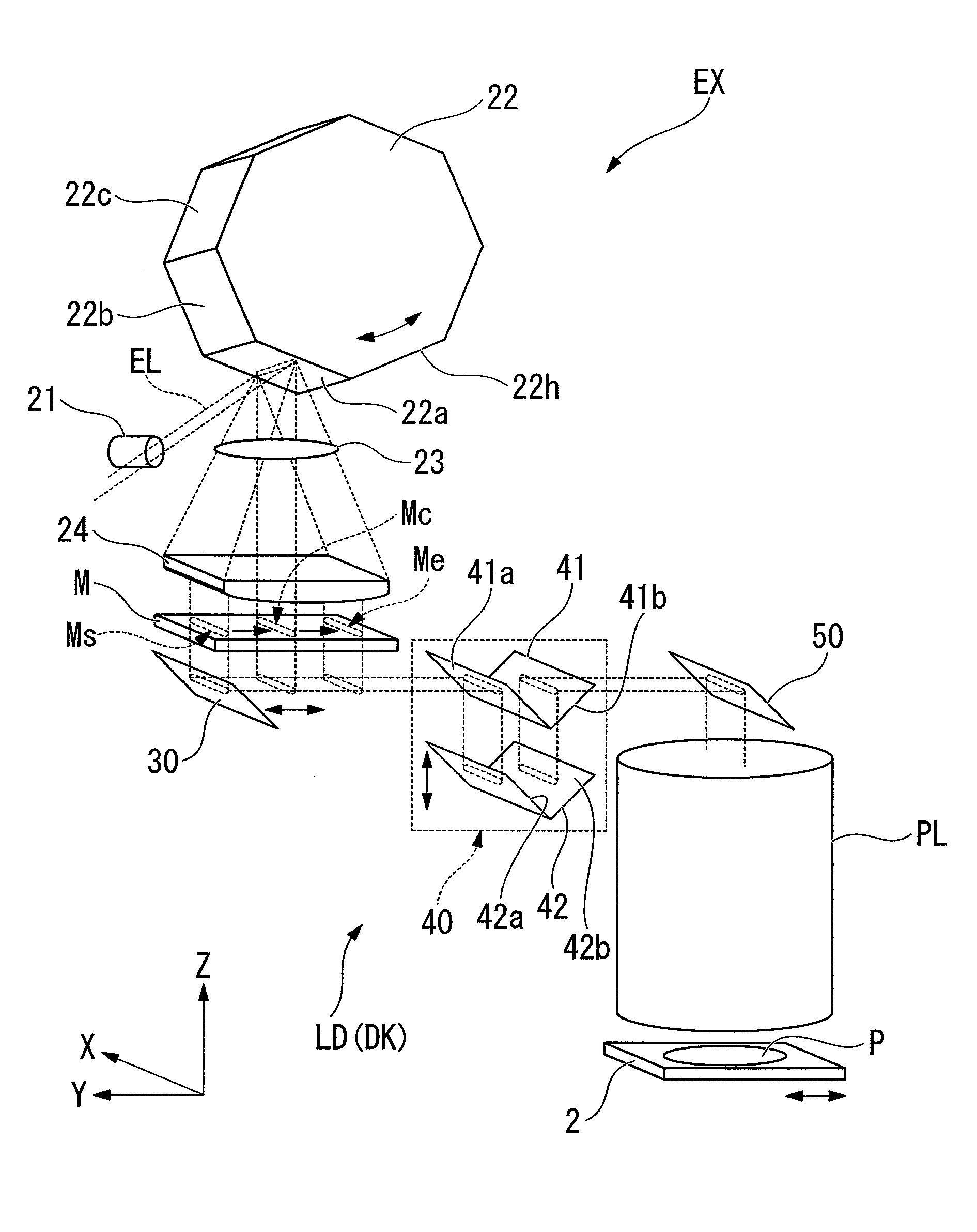
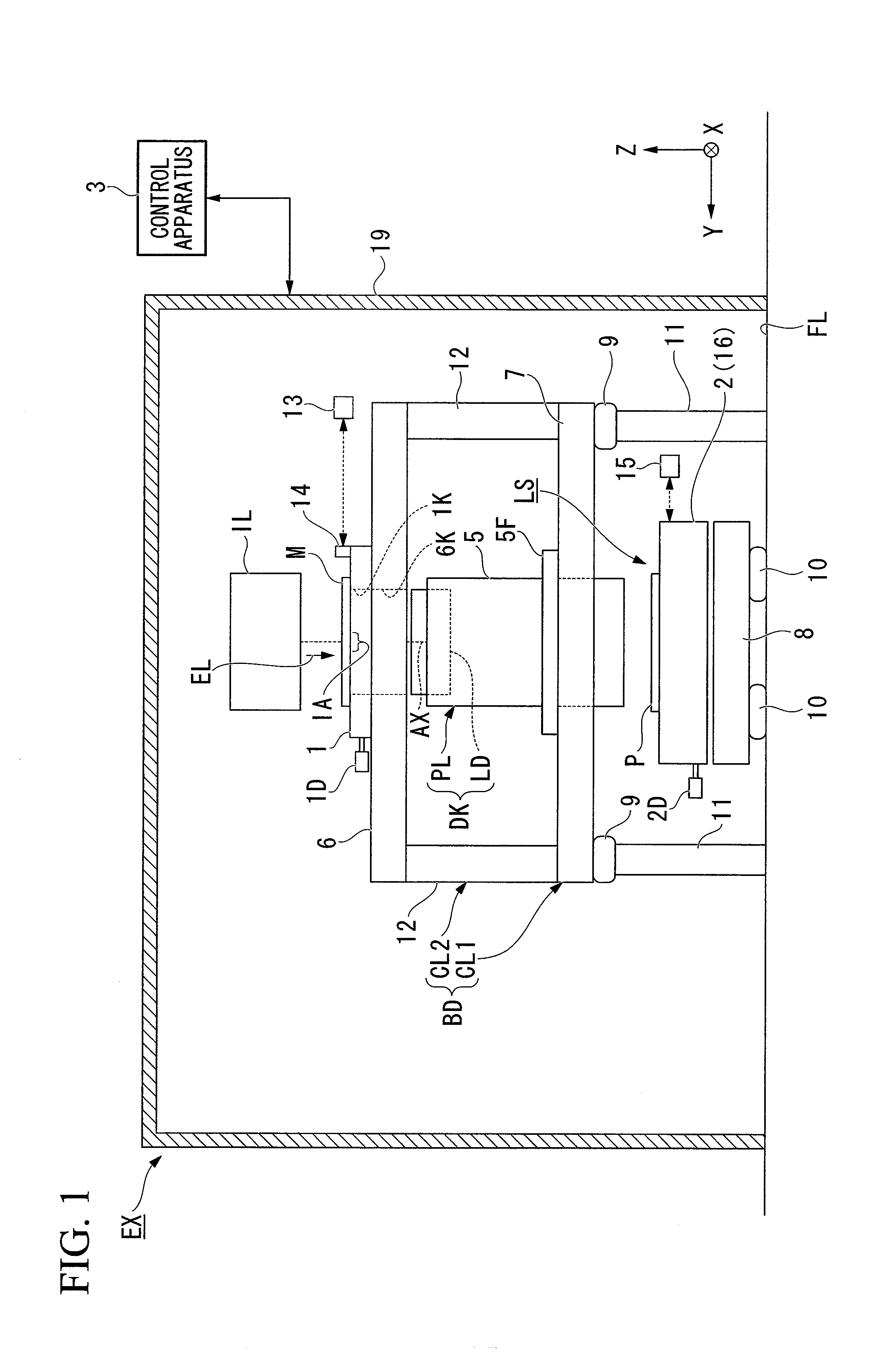
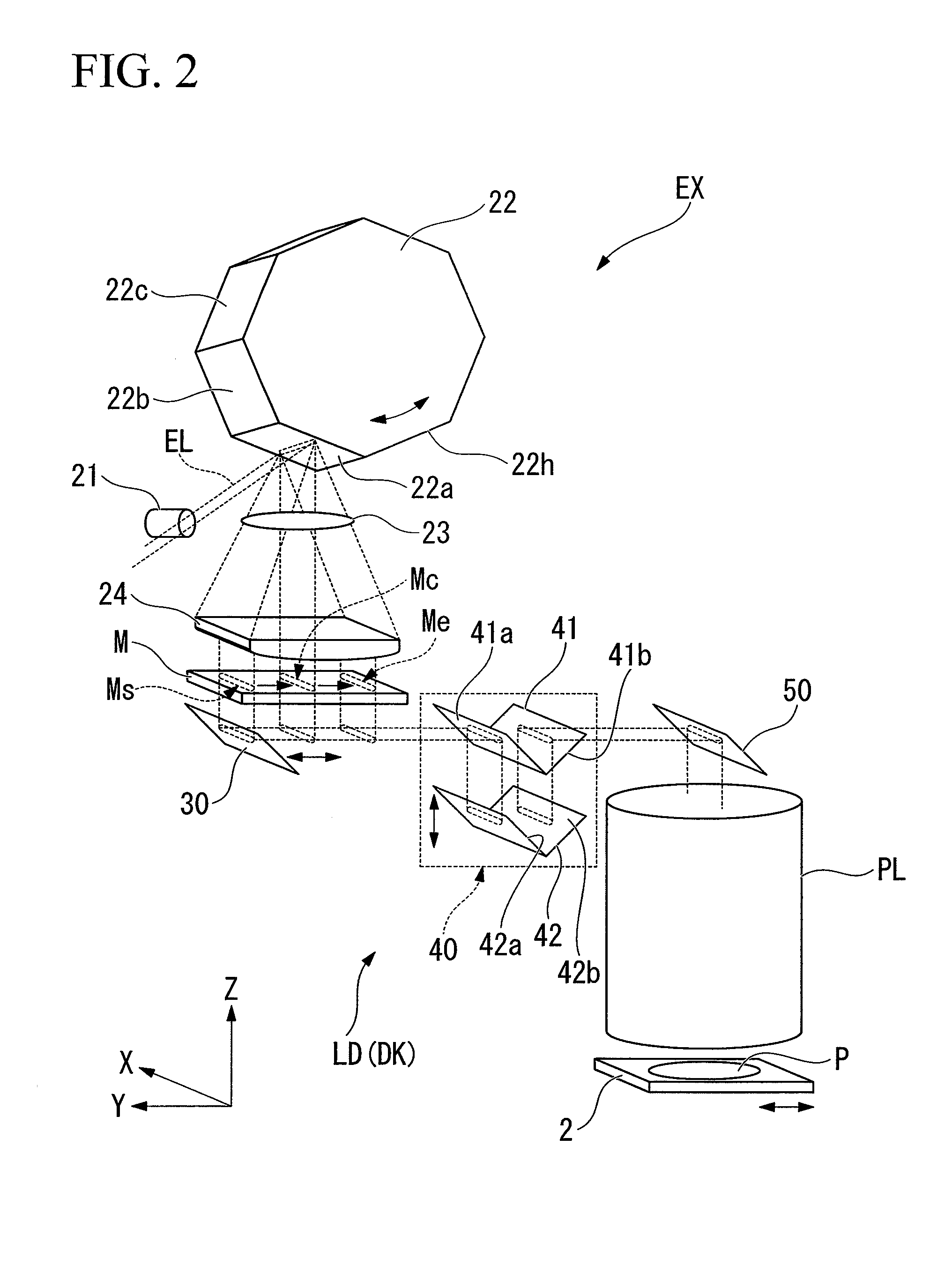
[0056]A first embodiment will be described. FIG. 1 is a schematic block diagram showing an exposure apparatus EX according to the first embodiment. In FIG. 1, the exposure apparatus EX includes; a mask stage 1 that is capable of holding and moving a mask M as a first object, a substrate stage (stage device) 2 that is capable of holding and moving a substrate P as a second object, an illumination system IL that illuminates a pattern of the mask M with exposure light (illuminating beam) EL, an optical guiding device DK that guides the exposure light EL illuminating the mask M to a shot field (area to be exposed) on the substrate P, and a control apparatus 3 that controls the operation of the overall exposure apparatus EX. The optical guiding device DK includes a projection optical system PL that projects an image of the pattern of the mask M illuminated by the exposure light EL onto the substrate P, and a conduction apparatus LD that causes the exposure light EL illuminating the mask ...

second embodiment

[0098]A second embodiment of the present invention will be described with reference to FIG. 6. The overall configuration of an exposure apparatus in the second embodiment is substantially the same as that of the exposure apparatus EX in the first embodiment shown in FIGS. 2 to 5, but the configuration of the reflecting mirror 30 is different.

[0099]FIG. 6 is a schematic block diagram showing the exposure apparatus according to the second embodiment. In FIG. 6, components the same as or similar to the abovementioned first embodiment shown in FIGS. 2 and 5 are denoted by the same reference symbols, and their description is omitted.

[0100]As shown in FIG. 6, in an exposure apparatus EX, a plurality of reflecting mirrors 30 and a plurality of reflecting mirrors 40 are provided. More specifically, in the exposure apparatus EX, the reflecting mirrors 30 and 40 are provided in the same number (four) as the maximum number (four) of shot fields in one line arranged on a substrate P in the scan...

third embodiment

[0106]Next, a third embodiment will be described with reference to FIG. 7. In the overall configuration of an exposure apparatus in the third embodiment, components such as the polygon mirror, the mask, and the optical guiding device are provided in pairs separately, to thereby perform simultaneous double exposure (multiple exposure) with respect to the exposure apparatus EX in the first embodiment shown in FIGS. 2 and 5. This will be described in detail. In FIG. 7, components the same as or similar to the abovementioned first embodiment shown in FIGS. 2 and 5 are denoted by the same reference symbols, and their description is omitted.

[0107]As shown in FIG. 7, in the exposure apparatus EX in the present embodiment, a correcting lens 21′, a polygon mirror 22′ (second scanning device), an fθ lens 23′, a telecentric lens 24′, a mask M′ (mask stage 1′, third object), and a second optical guiding device DK′ (conduction apparatus LD′) having the same configuration as a correcting lens 21,...


PUM


Abstract

An exposure apparatus illuminates a pattern on a first object with an illuminating beam to expose an area to be exposed on a second object with a pattern image. The exposure apparatus includes a scanning apparatus that scans the first object in a prescribed scanning direction with the illuminating beam, and an optical guiding device that guides the illuminating beam which has scanned the first object onto the area to be exposed on the second object.

Description

CROSS-REFERENCE TO RELATED APPLICATION[0001]This is a Continuation application of International Application No. PCT / JP2007 / 059717, filed May 11, 2007, which claims priority to Japanese Patent Application No. 2006-151208 filed on May 31, 2006. The contents of the aforementioned applications are incorporated herein by reference.BACKGROUND[0002]1. Field of the Invention[0003]The present invention relates to an exposure apparatus and an exposure method for exposing a pattern formed on a mask and transferring the pattern onto a substrate.[0004]2. Description of Related Art[0005]In manufacturing microdevices such as semiconductor devices, liquid crystal display devices, image pick-up devices (charge coupled devices (CCD) and the like), and thin-film magnetic heads, an exposure apparatus is used, which transfers a pattern formed on a mask or a reticle (hereinafter, generically termed a mask) onto a wafer or a glass plate (hereinafter, generically termed a substrate) applied with a photosen...

Claims


Application Information

Patent Timeline
IPC IPC(8): G03B27/42G03B27/54G03B27/32G03B27/70
CPCG02B26/125G03F7/70075G03F7/70583G03F7/70308G03F7/70258G03F7/70208G03F7/70358G03F7/7055
Inventor OKITA, SHINICHI
Owner NIKON CORP
Why Eureka
Eureka Blog
Learn More