Eureka AIR delivers breakthrough ideas for toughest innovation challenges, trusted by R&D personnel around the world.

Process for Making Environmental Reactant(s)

a technology of environmental reactants and reactants, applied in the field of reactants, can solve the problems of affecting the health of people, affecting the quality of environmental reactants, and affecting the quality of environmental reactants, and achieve the effect of convenient handling

Active Publication Date: 2009-03-05
SPECIALTY EARTH SCI
View PDF36 Cites 19 Cited by
  • Summary
  • Abstract
  • Description
  • Claims
  • Application Information

AI Technical Summary

Benefits of technology

"The present invention provides a method for making reactant(s) that can be used to treat hazardous organic contaminants in soil, sludge, groundwater, surface water, and wastewater. These reactant(s) can be easier to handle, persist in the contaminated areas, and react with the contaminants to form more innocuous materials. The method involves suspending or encapsulating the reactant(s) in a liquid and controlling the release and distribution of the reactant(s) through a targeted coating or encapsulant that targets the specific contaminants. The encapsulated reactant(s) can be used in either in situ or ex situ processes and can be introduced into different media simultaneously or at different locations. The method provides a means for remediation of soil, water, wastewater, and other environmental media."

Problems solved by technology

Discharges of hazardous organic compounds into the environment have led to contamination of surface water, soil, and aquifers resulting in potential public health problems and degradation of the land for future use.
In many cases, subsurface groundwater contaminant plumes may extend hundreds to thousands of feet from the source area of chemical release resulting in extensive contamination.
The presence of hazardous organic compounds in subsurface soils, surface water, and groundwater is a well-documented and extensive problem.
Soil, surface water, groundwater, and wastewater can become contaminated by a variety of substances.
This results in the subsurface dispersion of the reactant(s) within the area of the injection well.
Meeting USEPA cleanup criteria with these reactants and methods of the prior art has been found to be difficult, costly, and even impossible.
With some of these current methods and reactants, there has been questionable evidence that their application results in the effective or efficient removal of contaminants.
Current methods involving the use of peroxide group(s) (i.e. hydrogen peroxide) in conjunction with iron salt catalyst(s) are relatively inefficient, often resulting in incomplete contaminant oxidation.
Hydrogen peroxide in particular lacks persistence in contaminated soils and groundwater due to rapid dissociation.
Many of these current employed reactants are hazardous and difficult to handle.
However, known methods of permanganate use to actually remediate a site require exceedingly large quantities of permanganate(s) to overcome the natural oxidant demand exerted by the soil, thereby limiting the percentage available for oxidizing the hazardous organic compound(s).
Large amounts of permanganate(s) are thus required per unit of soil and groundwater volume, limiting the application of this technology due to high cost.
Additionally, a product of the permanganate(s) oxidation reaction is solid manganese dioxide which precipitates and clogs the soil or aquifer, resulting in a reduced permeability of the soil to water.
This reduced permeability in turn reduces the hydraulic conductivity thereby inhibiting oxidant access to the entire contaminated site and rendering treatment of the soil and hazardous organic compounds incomplete.
Further disadvantages of using permanganate(s) alone and in large quantities for subsurface remediation includes the formation of soluble manganese compounds in groundwater that may exceed drinking water standards.
For this and the foregoing reasons, attempts to date to use permanganate(s) for in situ remedial applications have not been fully successful.
However, the total amount of permanganate(s) and persulfate(s) required to treat a large area is still excessive and the extent to which the reactant(s) travel in the aquifer before being spent or reacted is insufficient.

Method used

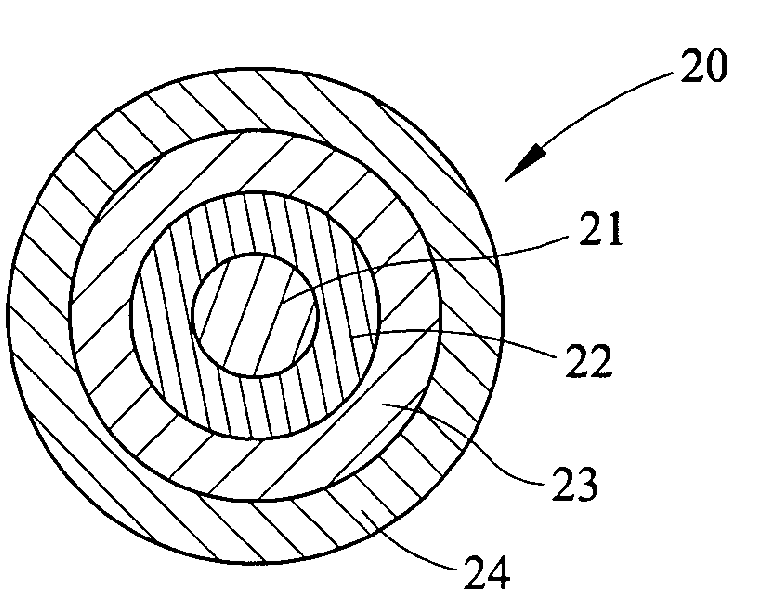
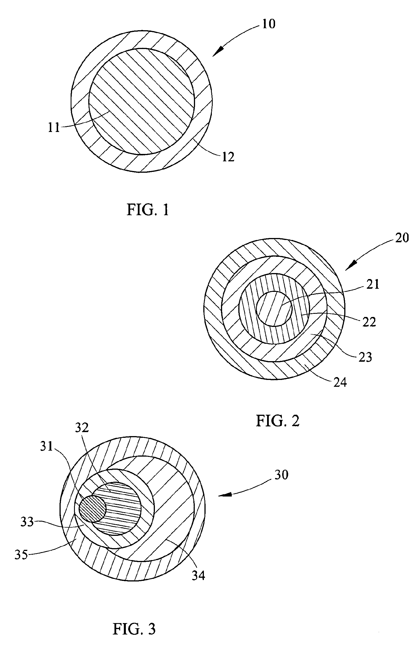

Image

  • Process for Making Environmental Reactant(s)
  • Process for Making Environmental Reactant(s)

Examples


example 1

[0053]Potassium permanganate (KMnO4) was milled in a media mill. The feed stock of KMnO4 had a first particle size of about 100-200 μm. The media mill was manufactured by Custom Milling & Consulting, Inc and had a milling shaft with a plurality of discs extending radially therefrom. The tip speed of the discs during milling was between about 1800 and 2500 fpm. The milling shaft extended into a cylindrical screen which was enclosed in a jacketed milling chamber. Cerium stabilized zirconium oxide milling media having about a 0.8 mm diameter was placed within the screen. The screen had slot openings smaller than the diameter of the milling media so as to retain the media therein. A discharge from the mixing chamber fed into a jacketed holding vessel. Material was accumulated in the holding vessel and was recirculated back through the mixing chamber. The particle size of the milled particles was then measured with a laser scattering analyzer in accordance with ASTM B822.

[0054]The millin...

example 2

[0055]The milling chamber and holding vessel of Example 1 were heated to a temperature of about 125° F. A coating material of paraffin wax was fed into the media mill of Example 1. KMnO4 of the first particle size of about 100-200 μm was fed into the milling chamber. The paraffin wax and KMnO4 were added to the milling chamber at weight a ratio of about 3:1. The milling shaft was rotated within the screen milling the KMnO4 for about 3 hours. An amount of KMnO4 and paraffin wax was continually discharged from the milling chamber into the holding vessel where it was recirculated back into the milling chamber. A sample of the milled KMnO4 was collected after 3 hours of milling at the point of discharge into the holding vessel and analyzed for particle size. The particle size of the oxidant particles are shown in Table 1.

example 3

[0056]Coating materials of mineral oil and paraffin wax were fed into a batch mill where the coating materials comprise 95% mineral oil and 5% paraffin. KMnO4 of the first particle size of about 100-200 μm was fed into the basket in the mill. The coating materials and KMnO4 were added to the milling vessel at weight a ratio of about 4:1. The KMnO4 was milled for about 3.5 hours. A sample of the milled KMnO4 was collected after 1, 1.5, 2, 3, and 3.5 hours of milling and analyzed for particle size. The particle size of the oxidant particles are shown in Table 1.

TABLE 1Mean oxidantCoating materialHours milledparticle size (μm)Hydrogenated soy bean wax12.5Hydrogenated soy bean wax21.8Hydrogenated soy bean wax31.4Hydrogenated soy bean wax41.5Paraffin31.695% mineral oil, 5% molten paraffin15.695% mineral oil, 5% molten paraffin1.54.395% mineral oil, 5% molten paraffin24.595% mineral oil, 5% molten paraffin33.695% mineral oil, 5% molten paraffin3.51.6

[0057]The data of Examples 1, 2, and 3 ...


PUM


Abstract

A process for making a reduced size oxidant particle is provided. The process forms reduced sized oxidant particles by feeding a coating material and oxidant particles of an initial size into a mill. The coating material may be oleophilic, hydrophobic, siliphilic, hydrocarbon soluble, or a combination thereof. The oxidant particles are then milled, reducing the particle size of the oxidant particles. During the milling step, the coating coats a substantial portion of each reduced sized oxidant particle reducing reagglomeration during the milling step. Optionally, the oxidant particles produced by the process of the instant invention are encapsulated. Alternatively or additionally, the oxidant particles may be placed in suspension. An outermost encapsulant may be substantially non-reacting, impermeable and non-dissolving with water. The oxidant particles formed by the process of the present invention may be placed directly into or in the path of the contaminant(s) in the environmental media to be treated. Processes for using the encapsulated reactant in environmental media are also hereby disclosed.

Description

CROSS-REFERENCE TO RELATED APPLICATIONS[0001]This application claims benefit under 35 U.S.C. § 120 and is a continuation-in-part of U.S. patent application Ser. No. 12 / 169,434, filed Jul. 8, 2008, which in turn is a continuation of and claims priority to U.S. patent application Ser. No. 11 / 072,118, filed Mar. 4, 2005 (now U.S. Pat. No. 7,431,849), which in turn claims priority to U.S. Provisional Application Ser. No. 60 / 550,799, filed Mar. 5, 2004, all of which are hereby incorporated by reference in their entirety.STATEMENT REGARDING FEDERALLY SPONSORED RESEARCH OR DEVELOPMENT[0002]Not applicable.FIELD OF INVENTION[0003]The present invention relates to reactant(s), methods for making said reactants, and methods for the in situ and ex situ remediation of hazardous organic compounds in soil, groundwater, and surface water.BACKGROUND OF THE INVENTION[0004]Discharges of hazardous organic compounds into the environment have led to contamination of surface water, soil, and aquifers resul...

Claims


Application Information

Patent Timeline
Patent Type & Authority Applications(United States)
IPC IPC(8): B05D7/24
CPCB01J13/04B01J13/22C02F2103/06C02F1/722C02F1/688
Inventor SWEARINGEN, JASONSWEARINGER, LINDSAY
Owner SPECIALTY EARTH SCI
Why Eureka
Eureka Blog
Learn More