Capacitance/voltage converting circuit, input apparatus using the same, electronic device, and capacitance/voltage converting method

Inactive Publication Date: 2009-02-26
ROHM CO LTD
View PDF5 Cites 12 Cited by
  • Summary
  • Abstract
  • Description
  • Claims
  • Application Information

AI Technical Summary

Benefits of technology

[0011]Also, the amplification unit may be a differential amplifier which receives the first detection voltage and the second detection voltage as the input signals. With such an arrangement, differential amplification is performed for the first detection voltage and the second detection voltage. Such an arrangement cancels the common mode noise, thereby properly detecting the difference in electrostatic capacitance.
[0014]Also, the capacitance / voltage conversion circuit may be integrated formed on a single semiconductor integrated circuit. Examples of arrangements integrally formed include: an arrangement in which all the components of a circuit are formed on a semiconductor substrate; an arrangement in which principal components of a circuit are integrally formed. With such an arrangement, adjusting components for adjusting circuit constants, such as a part of resistors, capacitors, etc., may be provided in the form of external components of the semiconductor substrate. With such an arrangement, the capacitance / voltage conversion circuit is integrally formed in the form of a single LSI, thereby reducing the circuit area.

Problems solved by technology

However, such an arrangement leads to an increased size of the input device.

Method used


Image

  • Capacitance/voltage converting circuit, input apparatus using the same, electronic device, and capacitance/voltage converting method
  • Capacitance/voltage converting circuit, input apparatus using the same, electronic device, and capacitance/voltage converting method
  • Capacitance/voltage converting circuit, input apparatus using the same, electronic device, and capacitance/voltage converting method

Examples


first embodiment

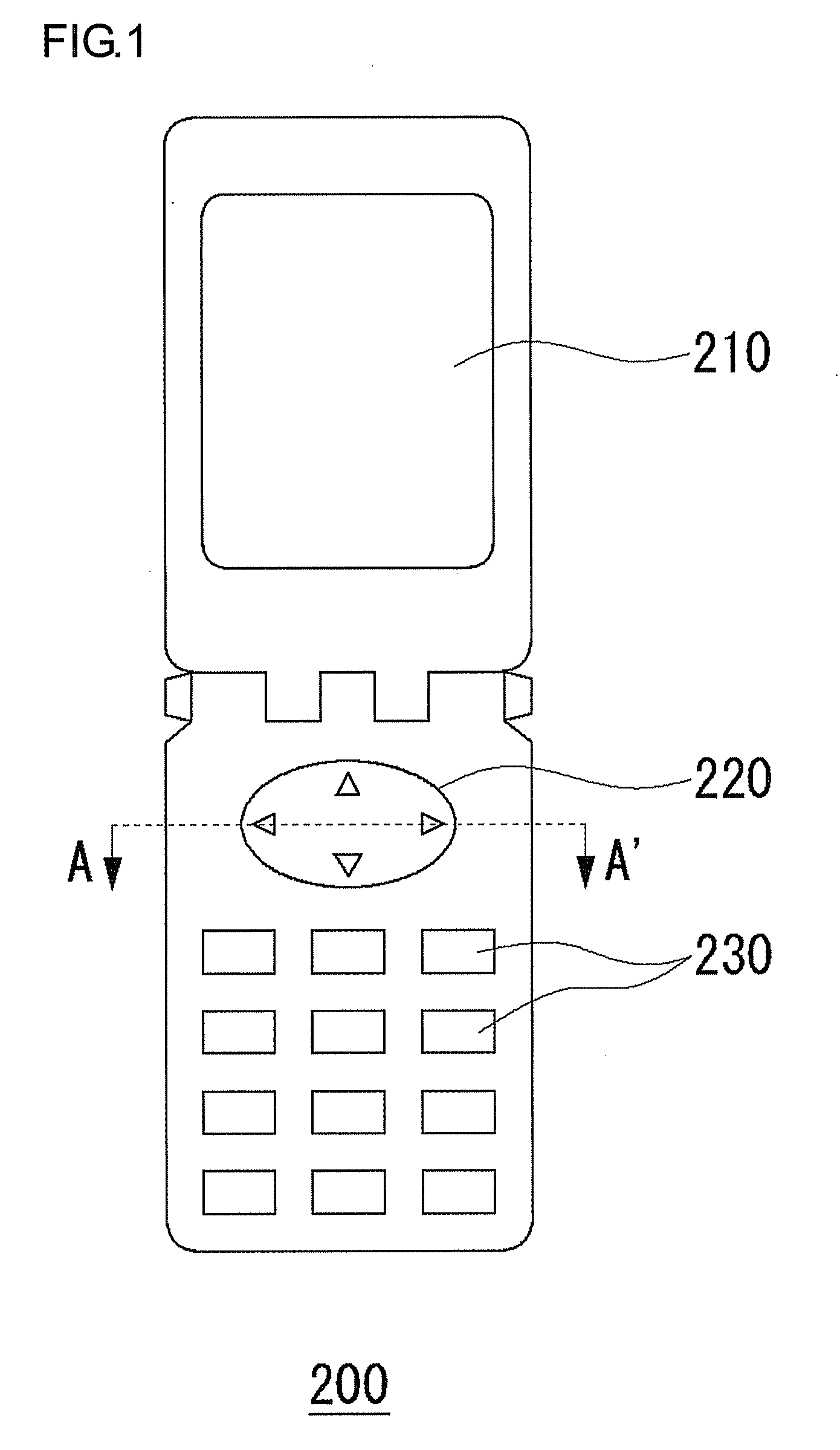
[0038]FIG. 1 is a diagram which shows a cellular phone terminal mounting an input device according to a first embodiment. A cellular phone terminal 200 includes a display 210, an input device 220, and operation buttons 230.

[0039]The display 210 displays various kinds of information necessary for the user. The input device 220 is an joystick type input device that allows the user to performs input operation with the user's fingers. Specifically, the input device 220 is mounted in order to provide a function that allows the user to select a desired item or object, and a function that supports character input operation, which operates according to the pressure applied by the user to a desired side selected from among the upper side, the left side, the lower side, and the right side.

[0040]The operation buttons are an input device which allows the user to input a phone number for a call, and which allows the user to input text.

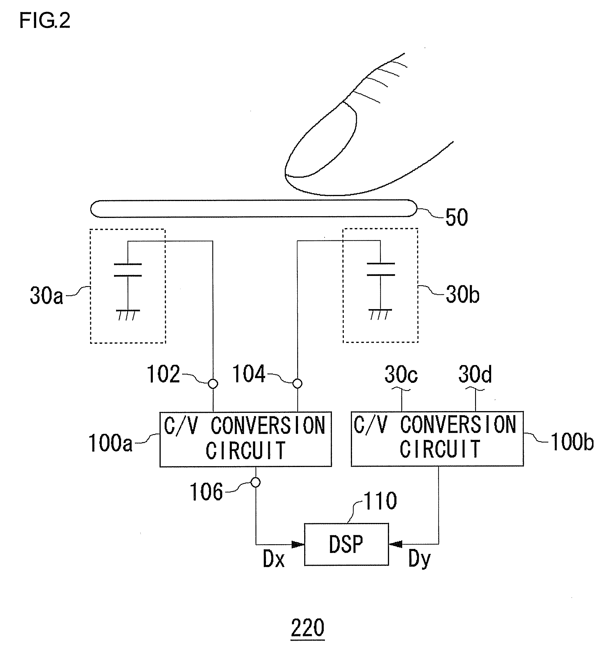
[0041]FIG. 2 is a cross-sectional view taken along line A-A′ ...

second embodiment

[0082]Description has been made in the first embodiment regarding an arrangement in which the four variable capacitance elements 30a through 30d are assigned to two groups, i.e., a group for detecting the pressure applied to the upper side or the lower side, a group for detecting the pressure applied to the left side or the right side. With such an arrangement, the difference in electrostatic capacitance is detected between the capacitors forming a capacitor pair. With the input device 220 having such a configuration, let us consider a case in which pressure is applied to the entire region including the variable capacitance elements 30a through 30d. In this case, a pair of the variable capacitance element 30a and 30b, or a pair of the variable capacitance element 30c and 30d, exhibits the same change in the electrostatic capacitance. Accordingly, with such an arrangement, in this case, the state due to the application of the pressure cannot be detected in increments of the variable ...

third embodiment

[0092]An input device according to a third embodiment is a touch pad type input device.

[0093]FIG. 6 is a diagram which shows a layout of capacitor pairs of an input device 222 according to the third embodiment. The input device 222 according to the third embodiment includes multiple capacitor pairs 300 disposed in the form of a matrix. Each capacitor pair 300 comprises a variable capacitance element 30 and a reference capacitor 32 in the same way as with the input device 220 according to the second embodiment. An unshown cover 50 is provided so as to cover the upper faces of these capacitor pairs 300 in the same way as with the input device 220 shown in FIG. 5.

[0094]Each capacitor pair 300 is connected to a corresponding one of multiple unshown capacitance / voltage conversion circuits 100. Each capacitance / voltage conversion circuit 100 detects the difference in electrostatic capacitance between the variable capacitance element 30 and the reference capacitor 32 included in the corres...


PUM


Abstract

A capacitance / voltage conversion circuit converts the difference in electrostatic capacitance between a first capacitor and a second capacitor into a voltage. With such an arrangement, a first voltage applying unit applies a power supply voltage Vdd to the first capacitor during a first state, and applies the ground voltage 0V to the first capacitor during a second state. A second voltage applying unit applies the ground voltage 0V to the second capacitor during the first state, and applies the power supply voltage Vdd to the second capacitor during the second state. A first sample hold circuit averages the voltage at the first capacitor and the voltage at the second capacitor in the first state by turning on a first switch and a second switch, and holds the voltage thus averaged as a first detection voltage Vdet1. In the same way, a second sample hold circuit averages the voltage at the first capacitor and the voltage at the second capacitor in the second state, and holds the voltage thus averaged as a second detection voltage Vdet2. An amplification unit performs differential amplification for the first detection voltage Vdet1 and the second detection voltage Vdet2.

Description

BACKGROUND OF THE INVENTION[0001]1. Field of the Invention[0002]The present invention relates to a capacitance / voltage conversion circuit used for measurement of electrostatic capacitance.[0003]2. Description of the Related Art[0004]In recent years, electronic devices such as computers, cellular phone terminals, PDAs (Personal Digital Assistants), etc., which have become mainstream, include an input device that allows a user to operate the electronic device by applying pressure with the user's finger. Examples of such known input devices include a joystick, a touch pad, etc.[0005]The input device includes a pair of electrodes provided such that they face one another. With such an input device, upon application of the pressure, the distance between the pair of electrodes changes, leading to a change in the electrostatic capacitance. Such an arrangement provides a function of detecting and analyzing the input operation from the user using a mechanism in which the electrostatic capacit...

Claims


Application Information

Patent Timeline
IPC IPC(8): G06F3/02G01R27/26
CPCH03K17/962
Inventor SAITO, KOICHI
Owner ROHM CO LTD
Why Eureka
Try Eureka