Transmission for electric bicycles for detecting a torque and related method for electric bicycles for detecting a torque

a technology of transmission and electric bicycles, applied in the direction of force/torque/work measurement apparatus, simultaneous indication of multiple variables, instruments, etc., can solve the problems of high cost of data evaluation and particularly prone to errors, and achieve the effect of not causing hysteresis

Inactive Publication Date: 2015-01-27
ROBERT BOSCH GMBH
View PDF14 Cites 3 Cited by
  • Summary
  • Abstract
  • Description
  • Claims
  • Application Information

AI Technical Summary

Benefits of technology

[0006]According to the present invention, the torque of the pedal crank that is to be measured is transferred to a sensor axis lying parallel to the pedal crank axis. Subsequently, the torque is conducted back again to a drive shaft that is rotatably supported coaxially on the pedal crank shaft or a drive shaft extending as an extension of the pedal crank shaft. Since in both transmissions sensor drives having different transmission ratios are used, that is, different sizes of the participating wheels, there comes about an overall force acting upon the sensor axis, and which is detected using a force sensor. The overall force is directly linked to the transmission ratios (which are constant) and the torque that is to be measured. The overall force may be deduced with the aid of the following system observation: Based on the energy received, the torques that are transmitted by the two sensor drives have to be different, since, in the same way (only reciprocally) the rotational speeds are different (friction being negligible in this case). Between the pedal crank shaft and the sensor shaft, due to this imbalance, there comes about an overall force which acts in the tangential direction of the torque transmission (i.e. the tangential motion of the rotational elements of the sensor transmission). Since the sensor transmissions pass on the rotational motion to a hollow shaft, which runs according to the longitudinal extension of the pedal crank shaft, the transmission according to the present invention is able to be used in a simple way in systems in which one may assume a single pedal crank shaft which is provided on the same axis of the pedal cranks and a drive element (e.g. a chain ring). The present invention may thus be integrated in a simple manner into known systems without a problem or introduced by exchange.
[0009]the pedal crank shaft on which the torque is acting and a hollow shaft, configured for connecting to a drive, through which the pedal crank shaft extends coaxially. This extension prevents problems caused by a radial offset. The hollow shaft is supported rotatably with respect to the pedal crank shaft, which may be by a roller bearing, inside the hollow shaft, which connects the hollow shaft and the pedal crank shaft. The transmission also includes a sensor shaft offset radially to the pedal crank shaft. Because of this offset, a force is generated on the drive side (and a counteracting force on the drive side) which acts on the sensor shaft. In addition, the transmission includes a force sensor connected to the sensor shaft, which detects a force exerted by the sensor shaft which is equivalent to the torque to be detected. The connection between the sensor shaft and the force sensor may be direct, for instance by fastening the force sensor to a bearing of the sensor shaft or to a frame which supports the sensor shaft.
[0012]One additional specific embodiment of the transmission, according to the present invention, provides that the transmission include a sensor frame in which the sensor shaft is rotationally supported. The force sensor is, on the one hand, connected to the sensor frame and, on the other hand, indirectly or directly to a housing element, which at least partially supports the pedal crank shaft or the hollow shaft. Furthermore, the power sensor may be provided between the sensor frame and an area that is also connected in a force-transmitting manner to the pedal crank shaft or the hollow shaft. The sensor is thereby able to detect the force difference on the frame which comes about because of the different transmission ratios. In addition, it is possible, because of this support, that a yielding force sensor is used whose position changes in response to different forces (increasing spring excursion with increasing force), since the frame and the sensor transmission permit an offset within certain limits, without the performance of the mechanical rotational motion transmission changing because of the transmission.
[0014]In particular, the drive-side sensor transmission may be developed by a pair of mutually engaging toothed wheels having outer toothing, and the output-side sensor transmission may be developed by a pair of mutually engaging toothed wheels. The drive-side or the output-side sensor transmission may be developed from a pair of mutually engaging outer toothings. At least one of the two pairs provides a mutually engaging outer toothing as a toothing which is developed directly on an outer side of the pedal crank shaft, of the sensor shaft or of the hollow shaft. The toothing of a toothed wheel engages in this outer toothing. As an alternative, the drive-side sensor transmission, the output-side sensor transmission or both sensor transmissions may each have the toothings of one pair. In this case, the toothing of a pair is an outer toothing of a toothed wheel, an outer toothing of the pedal crank shaft, the sensor shaft or the hollow shaft, or an inner toothing of a hollow wheel. The other toothing of the pair is an outer toothing of a toothed wheel that is mounted on the pedal crank shaft, the sensor shaft or the hollow shaft, or it is an outer toothing of the pedal crank shaft, the sensor shaft or the hollow shaft. These developments make possible the saving of space and component parts.
[0021]In contrast to numerous known sensors, the present invention also makes possible the reversal of the direction of rotation of the torque, without hysteresis being created during the measurement.

Problems solved by technology

For this reason, they are particularly prone to error.
In addition, the data evaluation required is costly.

Method used


Image

  • Transmission for electric bicycles for detecting a torque and related method for electric bicycles for detecting a torque
  • Transmission for electric bicycles for detecting a torque and related method for electric bicycles for detecting a torque
  • Transmission for electric bicycles for detecting a torque and related method for electric bicycles for detecting a torque

Examples


first embodiment

[0035]FIG. 2 shows the transmission according to the present invention, having crank 100, crank shaft 110 which is supported rotatably by bearings 130, 132, in order to be able to carry out a rotation according to arrow 112. On crank shaft 110, drive-side crank drive shaft wheel 150 is situated torsionally fixed and output-side hollow shaft wheel 160 is situated rotatably. Sensor shaft 40 has a drive-side sensor shaft wheel 152 and an output-side sensor shaft wheel 162, which are in engagement with wheels 150 and 160 respectively. The frame has an U-shaped extension, the two opposite legs having the rotary bearings 170′, 172′. The sensor shaft is rotatably supported in a frame 170 by rotary bearings 170′, 172′. The force is measured by a force sensor that is not shown, via which frame 170 is supported. The support not shown, via which the force sensor holds the frame, takes up forces in the tangential direction (with respect to the rotation of the sensor shaft or the pedal crank sha...

second embodiment

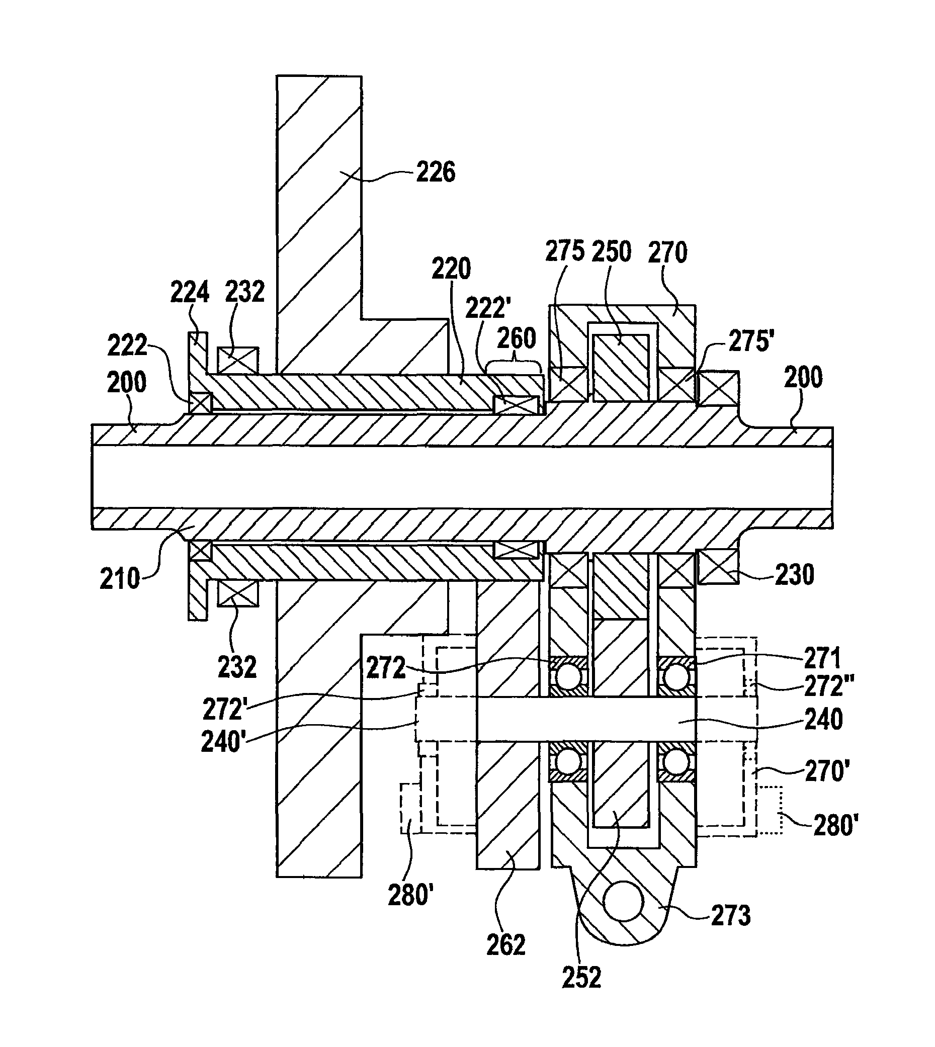
[0036]FIG. 3 shows the transmission according to the present invention, having a pedal crank shaft or crank shaft 210 at whose ends fastening elements 200 for pedal cranks are provided. On crank shaft 210, a hollow shaft 220 is rotatably supported via rotary bearings 222 and 222′. The crank shaft is supported on one side by a rotary bearing 230 and on the other side by a rotary bearing 232, which is located on the hollow shaft, via rotary bearing 222 between hollow shaft 220 and crank shaft 210 so that the crank shaft is also supported. Hollow shaft 220 at one end has a radially extending protuberance 224, which provides fastening elements (not shown) for the output drive.

[0037]A frame 270 is fastened on the pedal crank via rotary bearings 275 and 275′, which carries a sensor shaft 240 via rotary bearings 271, 272. On sensor shaft 240, a first wheel 252 (drive-side sensor shaft wheel) and a second wheel 262 (output-side sensor shaft wheel) are fastened, only one of the wheels (wheel...

third embodiment

[0040]FIG. 4 shows the transmission according to the present invention, having a pedal crank shaft or crank shaft 310, on which, at fastening locations 300′, cranks 300 are situated at both ends of crank shaft 310. On crank shaft 310, a hollow shaft 320 is rotatably supported via rotary bearings 222, 322′ that are offset axially with respect to each other. Hollow shaft 320 has at its end, that is opposite to the end of the hollow shaft that faces the sensor transmission, a connecting possibility (in the form of a protuberance 324) for a sprocket wheel 324 for driving a rear wheel of the bicycle. On hollow shaft 320 there is also situated a drive element in the form of a toothed wheel 326, via which an additional torque of a motor is able to be applied to hollow shaft 320. A rotary bearing 332 supports hollow shaft 320 (and consequently also crank shaft 310, and a rotary bearing 330 supports crank shaft 310 at the opposite end of crank shaft 310.

[0041]On crank shaft 310 a crank drive...


PUM


Abstract

A transmission for electric bicycles to detect a torque applied to a pedal crank shaft, includes a pedal crank shaft upon which the torque acts, a hollow shaft configured to connect to an output, through which the pedal crank shaft extends coaxially, and which is supported rotatably with respect to the pedal crank shaft, a sensor shaft offset in parallel with respect to the pedal crank shaft and a force sensor connected to the sensor shaft. The transmission includes a drive-side sensor transmission and an output side sensor transmission. The drive-side sensor transmission connects the pedal crank shaft to the sensor shaft and the output-side sensor transmission connects the sensor shaft to the hollow shaft, which is configured to be connected to an output, and the drive-side sensor transmission has a gear ratio which differs from the gear ratio of the output-side sensor transmission. A corresponding method is also described.

Description

FIELD OF THE INVENTION[0001]The present invention relates to a transmission for electric bicycles to detect a torque applied to a pedal crank shaft.BACKGROUND INFORMATION[0002]In the field of the present invention, i.e. particularly the field of electric bicycles and related pedal force sensors, there are mechanisms for torque detection, in order to conclude upon the cyclist power with the aid of the torque with which the pedal crank is being actuated. The cyclist power or a comparable quantity is used as an input quantity in the regulation of an electric auxiliary motor of electric bicycles. The sensors used are provided directly at exposed locations and fastened to elements via which the entire torque is transmitted. For this reason, they are particularly prone to error.[0003]Besides solutions in which a force is ascertained directly by detection at the pedal crank shaft or by force sensors situated on the pedals, there are approaches that are in German document DE 698 20 41 T2. I...

Claims


Application Information

Patent Timeline
Patent Type & Authority Patents(United States)
IPC IPC(8): B62M6/50B62M3/16G01D7/02
CPCB62M3/16B62M6/50G01D7/02Y10T74/2164
Inventor AYDOGAN, SERDARZLINDRA, MARTINBRAUN, SIGMUND
Owner ROBERT BOSCH GMBH
Why Eureka
Try Eureka