Apparatus for and Method of Manufacturing Photosensitive Laminated Body

a technology of laminated body and apparatus, which is applied in the direction of lamination ancillary operations, chemistry apparatus and processes, domestic applications, etc., can solve the problems of large photosensitive sheet in the form of a roll, inability to efficiently handle the roll, and the reel-out mechanism, etc., to achieve simple process and arrangement, easy to handle

Inactive Publication Date: 2009-02-26
FUJIFILM CORP
View PDF0 Cites 7 Cited by
  • Summary
  • Abstract
  • Description
  • Claims
  • Application Information

AI Technical Summary

Benefits of technology

[0011]A principal object of the present invention is to provide an apparatus for and a method of manufacturing a photosensitive laminated body, which is easy to handle, by reliably attaching two or more elongate photosensitive webs parallel to each other to substrates through a simple process and arrangement.
[0021]As a result of the above features, at least two photosensitive material layers that are transversely spaced from each other can be transferred effectively onto a wide substrate, and a high-quality photosensitive laminated body can efficiently be produced. Further, in the elongate photosensitive webs, residual stresses within the resin layer are reliably mitigated, and the support can be easily and favorably peeled off from the resin layer.

Problems solved by technology

However, a wider photosensitive sheet in the form of a roll cannot be handled efficiently with ease, and a reel-out mechanism for unreeling the photosensitive sheet from the roll is also larger in size.
The wider photosensitive sheet is heavier, is more liable to develop wrinkles therein, and is more difficult to handle.

Method used


Image

  • Apparatus for and Method of Manufacturing Photosensitive Laminated Body
  • Apparatus for and Method of Manufacturing Photosensitive Laminated Body
  • Apparatus for and Method of Manufacturing Photosensitive Laminated Body

Examples


first embodiment

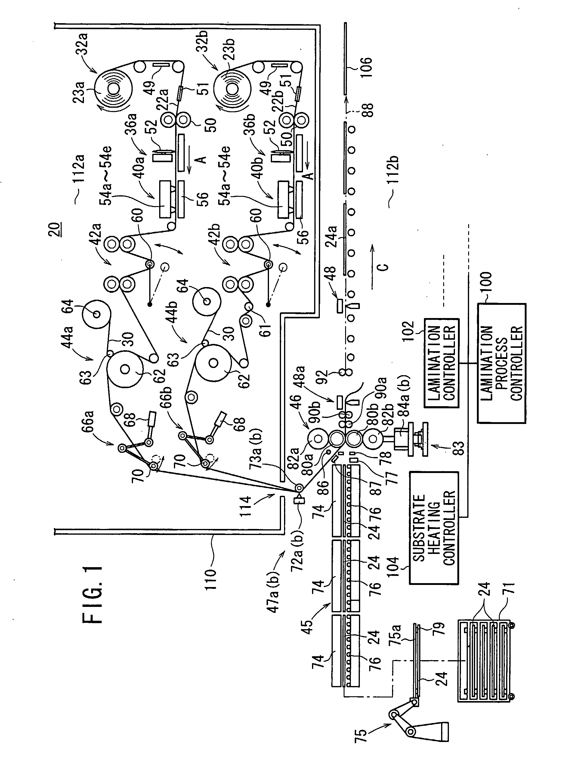
[0073]FIG. 1 shows in schematic side elevation an apparatus 20 for manufacturing a photosensitive laminated body according to the present invention. The manufacturing apparatus 20 operates to thermally transfer respective photosensitive resin layers 28 (described later) of elongate photosensitive webs 22a, 22b parallel to each other to glass substrates 24 in a process of manufacturing liquid crystal or organic EL color filters. The photosensitive webs 22a, 22b have such respective widths that the elongate photosensitive web 22a is wider than the photosensitive web 22b, for example.

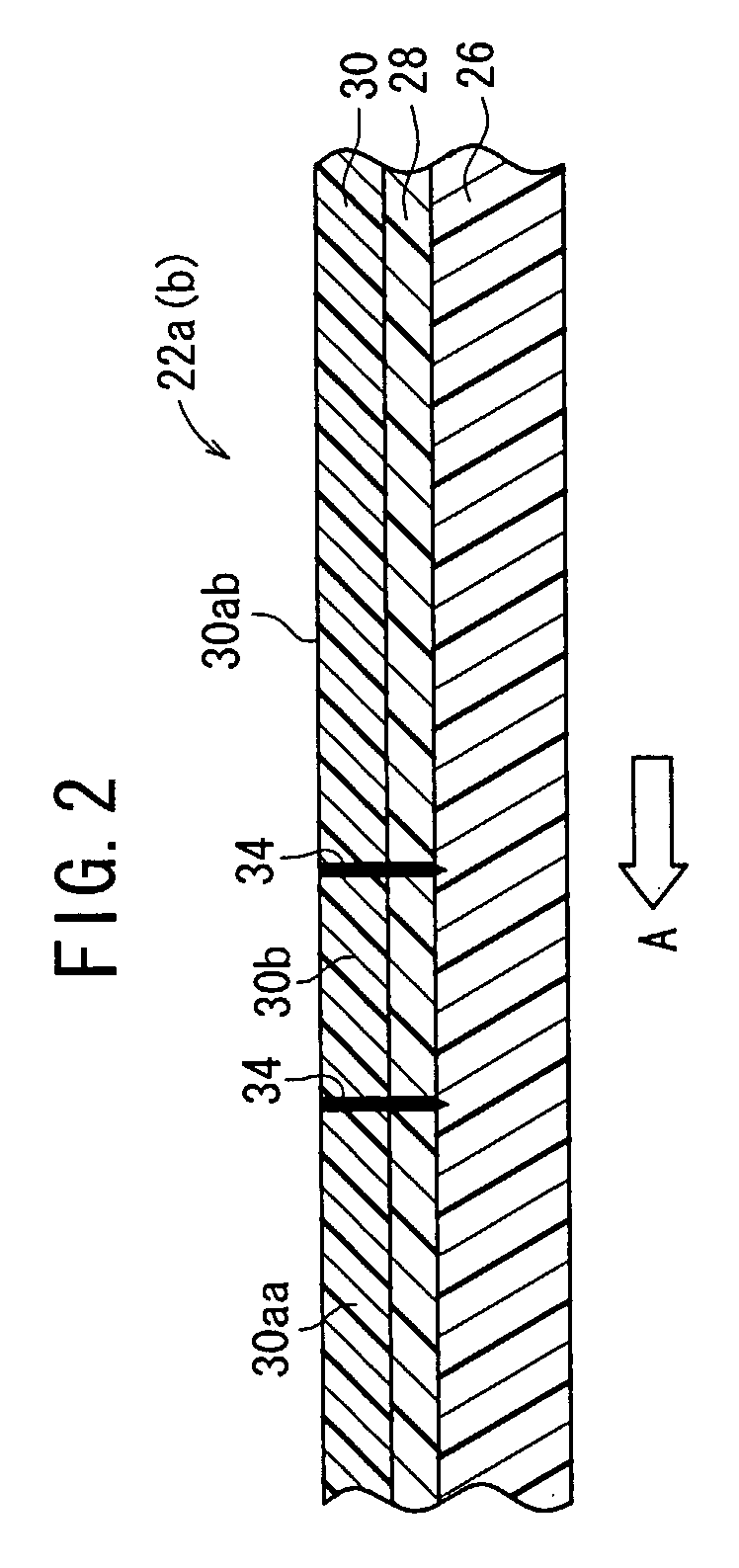
[0074]FIG. 2 shows in cross section each of the photosensitive webs 22a, 22b that are employed in the manufacturing apparatus 20. Each of the photosensitive webs 22a, 22b comprises a laminated assembly of a flexible base film (support) 26, a photosensitive resin layer (photosensitive material layer) 28 disposed on the flexible base film 26, and a protective film 30 disposed on the photosensitive resin laye...

second embodiment

[0166]In the first and second detecting mechanisms 121a, 121b the photoelectric sensors 123a, 123c which are positioned upstream of the photoelectric sensors 123b, 123d first detect the partially cut regions 34 of the photosensitive webs 22a, 22b. Thereafter, the downstream photoelectric sensors 123b, 123d detect the partially cut regions 34 of the photosensitive webs 22a, 22b. The distance L between the backup rollers 73a, 73c and the backup rollers 73b, 73d corresponds to the length of each of the photosensitive resin layers 28 applied to the glass substrate 24.

[0167]The actual applied lengths of the photosensitive resin layers 28 can accurately be calculated from the difference between the time when the upstream photoelectric sensors 123a, 123c detect the partially cut regions 34 of the photosensitive webs 22a, 22b and the time when the downstream photoelectric sensors 123b, 123d detect the same partially cut regions 34 of the photosensitive webs 22a, 22b. Based on the calculate...

third embodiment

[0179] the attached substrate 24a to which the photosensitive webs 22a, 22b are laminated is cooled by the cooling mechanism 122 and then delivered to the pre-peeler 144. In the pre-peeler 144, the nip roller assemblies 152, 154 grip the trailing and leading ends of two adjacent glass substrates 24, and the nip roller assembly 152 moves in the direction indicated by the arrow C at the same speed as the glass substrates 24, with the nip roller assembly 154 being decelerated in its travel in the direction indicated by the arrow C.

[0180]Consequently, as shown in FIG. 30, the photosensitive webs 22a, 22b between the glass substrates 24 are flexed between the nip roller assemblies 152, 154. Then, the peeling bar 156 is lifted to push the photosensitive webs 22a, 22b upwardly, peeling the projecting films 30 off from the trailing and leading ends of the two adjacent glass substrates 24.

[0181]In the automatic base peeling mechanism 142, the takeup roll 148 is rotated to continuously wind t...


PUM

PropertyMeasurementUnit
speedaaaaaaaaaa
temperatureaaaaaaaaaa

Abstract

A manufacturing apparatus (20) has first and second reel-out mechanisms (32a, 32b), first and second processing mechanisms (36a, 36b), first and second label bonding mechanisms (40a, 40b), first and second reservoir mechanisms (42a, 42b), first and second peeling mechanisms (44a, 44b), a substrate feed mechanism (45), an attachment mechanism (46), and a base peeling mechanism (186). A cooling mechanism (122) is disposed between the attachment mechanism (46) and the base peeling mechanism (186), for cooling an attached substrate (24a), the attached substrate (24a) being made up of a glass substrate (24) and a photosensitive web (22) attached thereto, from which a protective film (30) has been peeled off, together with a heating mechanism (182) for heating a resin layer, for example a cushion layer (27), inside the cooled attached substrate (24a) to within a predetermined temperature range, which is at or below the glass transition temperature.

Description

TECHNICAL FIELD[0001]The present invention relates to an apparatus for and a method of manufacturing a photosensitive laminated body by delivering two or more elongate photosensitive webs each comprising a photosensitive material layer and a protective film that are successively deposited on a support, peeling off the protective films to expose the photosensitive material layers, and attaching the exposed photosensitive material layers parallel to each other to substrates.BACKGROUND ART[0002]Substrates for liquid crystal panels, substrates for printed wiring boards, and substrates for PDP panels, for example, have a photosensitive sheet (photosensitive web) having a photosensitive material (photosensitive resin) layer and applied to a substrate surface. The photosensitive sheet comprises a photosensitive material layer and a protective film that are successively deposited on a flexible plastic support.[0003]An applying apparatus for applying such a photosensitive sheet usually opera...

Claims


Application Information

Patent Timeline
Patent Type & Authority Applications(United States)
IPC IPC(8): B32B38/10B32B37/08B32B38/00B32B37/06
CPCB32B37/223B32B38/0004B32B38/10B32B38/185B32B2038/1891B32B2457/00B32B2457/08B32B2559/00B32B37/22B32B38/18B32B38/00
Inventor SUEHARA, KAZUYOSHIAKIYOSHI, NOBUYASUIMOTO, KENICHISUGIHARA, RYOICHIMORI, RYOSUZUKI, CHIAKI
Owner FUJIFILM CORP
Why Eureka
Try Eureka