
Eyeless Sewing Needle and Fabrication Method for the Same

a sewing needle and fabrication method technology, applied in the field of eyeless sewing needles, can solve the problems of easy cracking, chipping or the like, corrosion resistance, and difficult processing such as crimping to attach a suture thread to the sewing needle, and achieve the effect of facilitating crimping and related operations, ensuring strength, and easy bend

Active Publication Date: 2009-02-12
MATSUTANI SEISAKUSHO CO LTD
View PDF7 Cites 11 Cited by
  • Summary
  • Abstract
  • Description
  • Claims
  • Application Information

AI Technical Summary

Benefits of technology

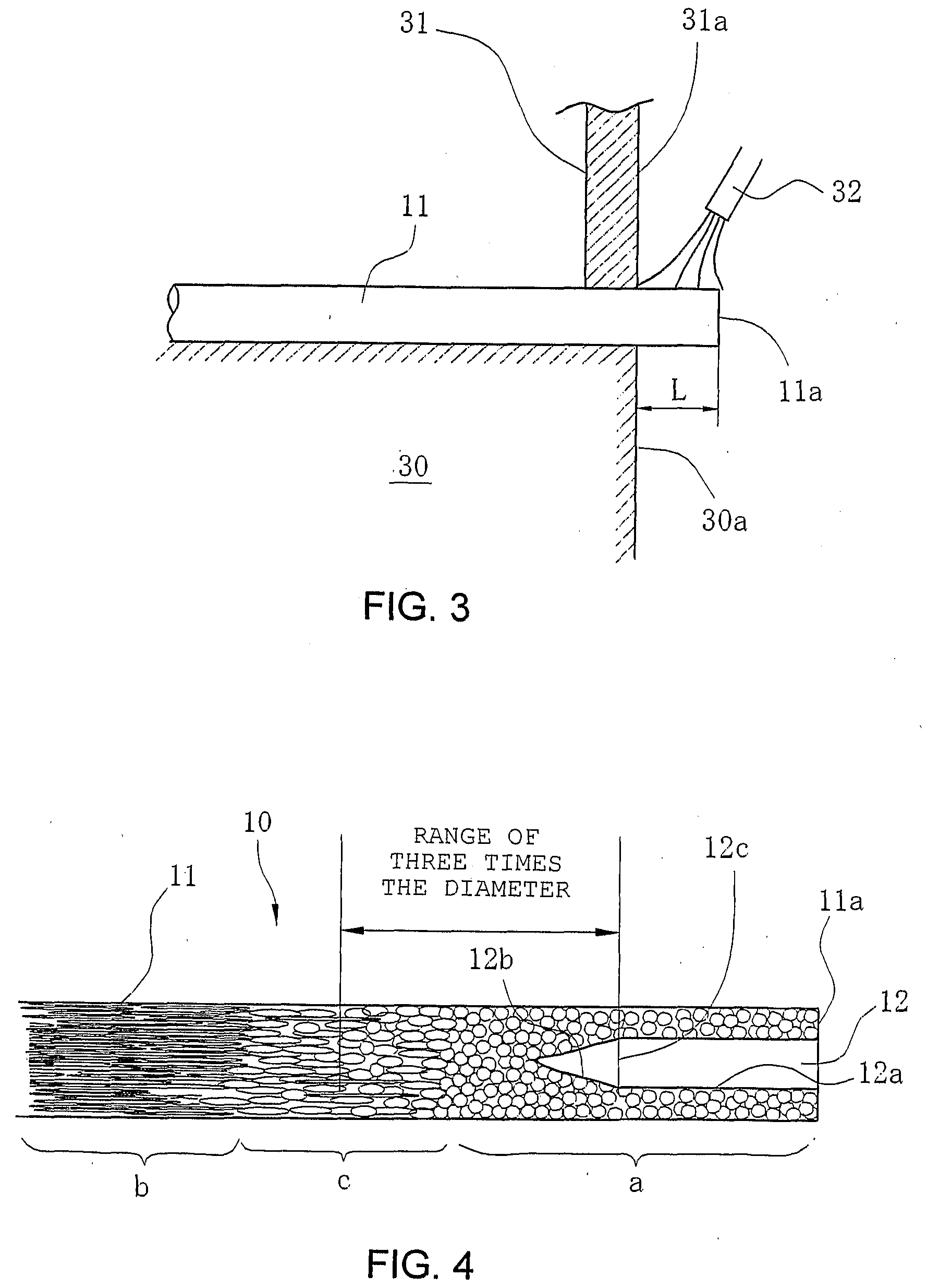
The present invention provides an eyeless sewing needle that is flexible at the hole and has a high hardness at a position slightly away from the hole towards the needlepoint side. The needle has a curved axial main body with an axial hole extending from the base end to the sharp needlepoint. The needle has a flexible periphery near the hole that allows for easy crimping and suturing. The needle is heated to make the periphery a granular structure without directionality, and a heat-affected zone is formed between the fibrous structure and the granular structure. The heat-affected zone is located at a position three times the diameter of the needle and extends towards the needlepoint. The needle remains strong and secure while being gripped with a needle holder, and it is convenient for eyeless sewing.

Problems solved by technology

Since the above materials are soft, processing is easy, but there is a problem with quenching and precipitation hardening in that cracking, breaking, chipping, or the like easily occurs due to lack of toughness.
Furthermore, there is a problem with corrosion resistance since rust easily develops due to characteristics of the materials.
However, since the entirety from the tip to the base end is a fibrous structure, it is hard, and processing such as crimping to attach a suture thread to the sewing needle is difficult.
Furthermore, the hole cracks even due to crimping, causing damage to the anatomy, which thereby reduces tension of the suture thread, making it easier to pull out.
Therefore, if a surgeon grips near the hole of the sewing needle when suturing, there is a problem that he / she grasps a flexible granular structure, resulting in a bent sewing needle.
Needing to always grip on the tip side of the needle is stressful for the doctor.

Method used


Image

  • Eyeless Sewing Needle and Fabrication Method for the Same
  • Eyeless Sewing Needle and Fabrication Method for the Same
  • Eyeless Sewing Needle and Fabrication Method for the Same

Examples


Embodiment Construction

[0021]An embodiment according to the present invention is described with reference to accompanying drawings forthwith.

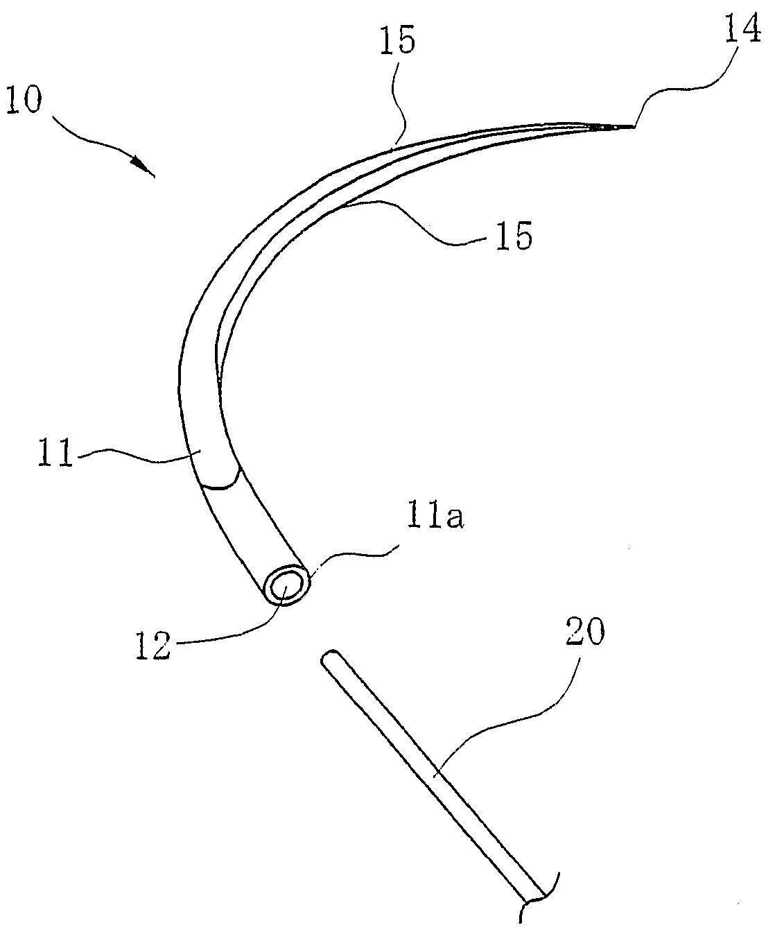
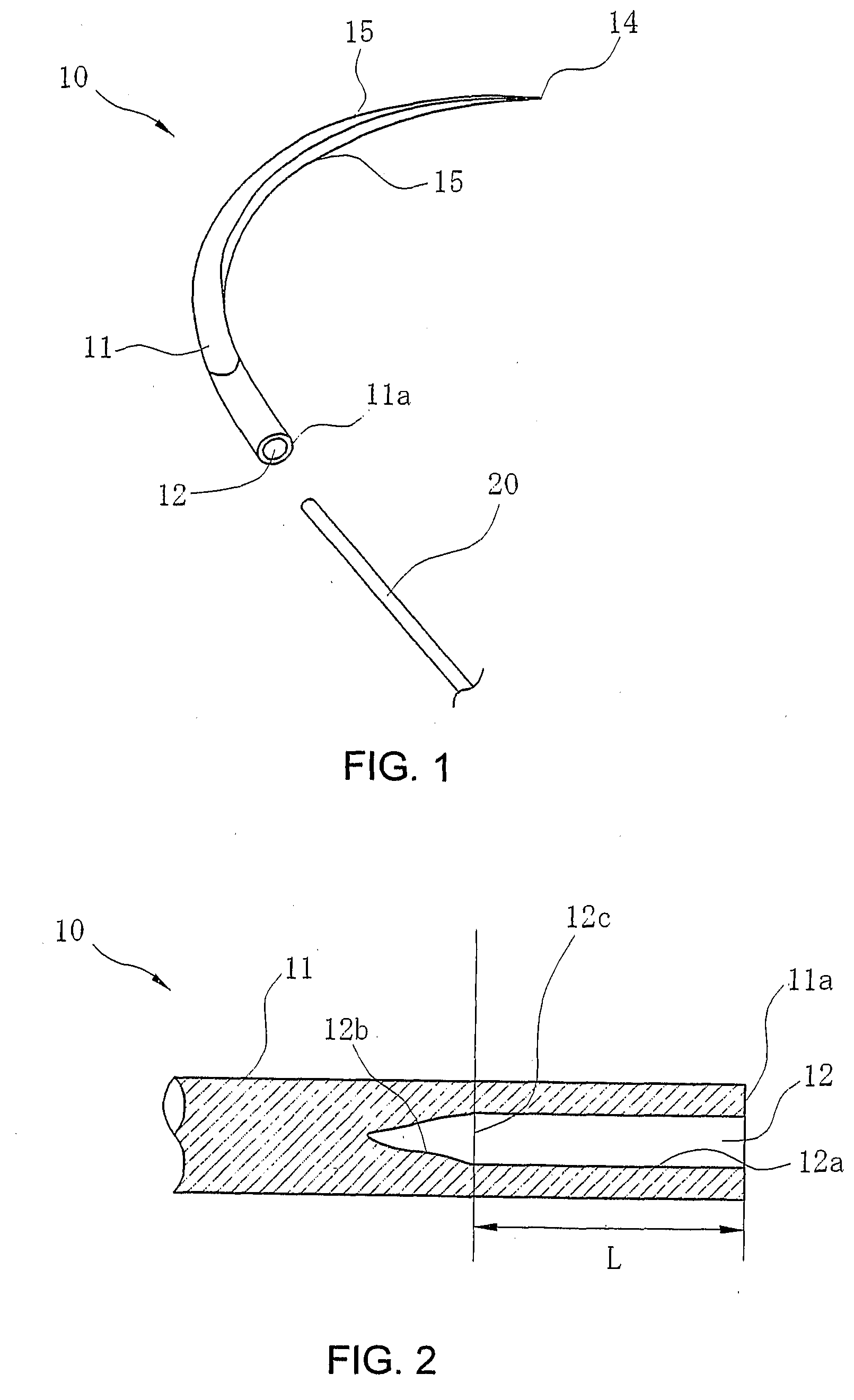
[0022]FIG. 1 is an oblique perspective of an eyeless sewing needle according to the present invention. As shown in this diagram, an eyeless sewing needle 10 is entirely made of austenitic stainless steel, a base end 11a is on an end of a main body 11, and an axial hole 12 is formed in this base end 11a which is cylindrically drilled along the longitudinal axis of the needle according to a processing method using a laser, an electron beam, electric discharge, a drill, or the like. Furthermore, a sharp needlepoint 14 is formed at the tip of the eyeless sewing needle 10, and a pyramid having a plurality of cutting blades 15 continuing from the needlepoint 14 is formed.

[0023]The eyeless sewing needle 10 may be a sewing needle with a sharpened edge (not shown in the drawing) in which the cross section of the cutting blades 15 as shown in FIG. 1 is formed into a polygon, a...


PUM

PropertyMeasurementUnit
diameteraaaaaaaaaa
temperatureaaaaaaaaaa
crystalline structureaaaaaaaaaa

Abstract

In an eyeless sewing needle, a periphery of an axial hole at the base end is heated to make a fibrous structure be a granular structure without directionality, and at least a part of a heat-affected zone made between the fibrous structure and the granular structure due to the heating is within a range that is three times the diameter of the sewing needle and that extends from an effective base of the axial hole towards the needlepoint. This allows provision of a flexible sewing needle so that the hole periphery can be processed while keeping a hard state at the position of the needlepoint slightly away from the axial hole.

Description

TECHNICAL FIELD[0001]The present invention relates to an eyeless sewing needle and a fabrication method for the same. It particularly relates to an eyeless sewing needle made of austenitic stainless steel having a fibrous crystalline structure extending along the length of the sewing needle.BACKGROUND ART[0002]Stainless steel is a suitable material for sewing needles to be used in surgical operations. In the case of martensitic stainless steel, precipitation hardening stainless steel, or the like, wire rods each 6 to 10 mm in diameter are used as the material. In the case of carbon steel or martensitic stainless steel, wire drawing is carried out repeatedly thereto, providing wires each having the diameter of a sewing needle being fabricated. In the case of stainless steel, a solution heat treatment is carried out between each wire drawing.[0003]These wires are cut at an appropriate length, and tips thereof are then sharpened by grinding using a grindstone into a cone or pyramid sha...

Claims


Application Information

Patent Timeline
Patent Type & Authority Applications(United States)
IPC IPC(8): D05B85/06B23P11/00
CPCA61B17/06066A61B2017/06028C21D1/26Y10T29/49826C21D1/52C21D9/26C21D2211/001C21D1/30B21G1/08A61B17/06
Inventor MASHIKO, MASAKIMATSUTANI, KANJISHINOHARA, KOSUKEAKABA, MIEKO
Owner MATSUTANI SEISAKUSHO CO LTD
Learn More