
Control Grid for Solar Energy Concentrators and Similar Equipment

Inactive Publication Date: 2009-02-12
RABINOWITZ MARIO
View PDF30 Cites 2 Cited by
  • Summary
  • Abstract
  • Description
  • Claims
  • Application Information

AI Technical Summary

Benefits of technology

[0043]It is another aspect of the present invention to increase the longevity and performance of said grid.
[0052]Although the cost per unit weight may appear high, the cost per manufactured grid can be significantly lower than ITO, not only because of the lower atomic weight and lower density of carbon, but because of the greater strength and manufacturability ease of carbon nanotubes.

Problems solved by technology

Thus troublesome and expensive grid material like Indium Tin Oxide (ITO) can be replaced by more manageable, hardier, and in the long run relatively less expensive nanotubes, or a carbon grid simply laid down by ordinary photocopy reduction techniques.

Method used


Image

  • Control Grid for Solar Energy Concentrators and Similar Equipment
  • Control Grid for Solar Energy Concentrators and Similar Equipment

Examples


Embodiment Construction

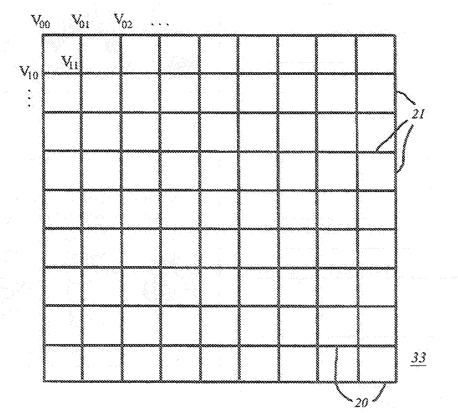
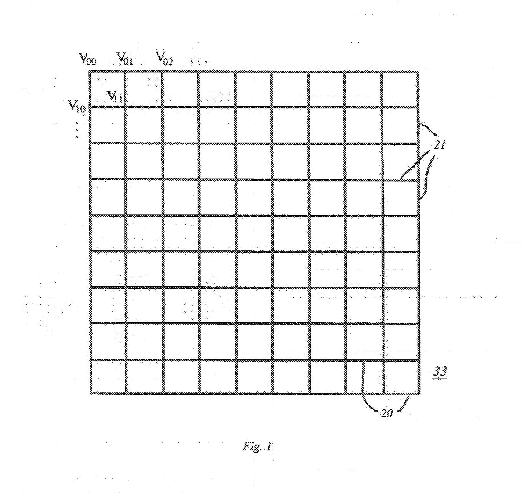
[0046]For those solar concentrators that can afford to lose a small percentage of transparency on the side facing the sun, there is no need for the transparency of ITO. The grid could be drawn on paper, and Xerographically (or photographically) de-magnified (reduced) repeatedly until the resolution limit is reached. In the final step a thin plastic sheet would be used upon which the final Xerographic carbon grid would be laid down. The final reduced copy has a thin carbon grid laid down on a flexible transparent sheet for the top of the equipment. The carbon for the final step can be either the usual carbon particle mix used in standard Xerography, or preferably a mix containing carbon nanotubes. A similar grid sheet that is put on the bottom of the equipment, need not be transparent. However, if a transparent grid sheet is also used on the bottom of the equipment, the potential is retained for turning the equipment over and utilizing the bottom as the new top side, if needed. One l...


PUM


Abstract

This invention provides a better means to achieve affordable solar energy, as well as other technologies. It does so by improving control grids (for addressing and alignment) in solar concentrators and optical equipment in general. Thus troublesome and expensive grid material like Indium Tin Oxide (ITO) can be replaced by more manageable, hardier, and in the long run relatively less expensive nanotubes; or a carbon grid simply laid down by ordinary photocopy (Xerographic) reduction techniques. The instant invention relates to improvements in the control (addressing and alignment) grid for Solar Energy Concentrators; and similar equipment such as Optical Switches [e.g. cf. M. Rabinowitz U.S. Pat. No. 6,976,445]; and Display devices such as Dynamic Reflection, Illumination, and Projection equipment [e.g. cf. M. Rabinowitz U.S. Pat. No. 7,130,102]; as well as display equipment in general. The control grid acts to address and align active optical elements such as mirrored balls, multipainted balls, electrophoretic, and magnetophoretic cells in solar concentrators [e.g. cf. M. Rabinowitz U.S. Pat. Nos. 7,133,183 and 6,843,573]; and in other equipment. Methods of fabricating the grids are also described.

Description

FIELD OF THE INVENTION[0001]The instant invention relates to improvements in the control (addressing and alignment) grid for Solar Energy Concentrators; and similar equipment such as Optical Switches [e.g. cf. U.S. Pat. No. 6,976,445 by M. Rabinowitz]; and Display devices such as Dynamic Reflection, Illumination, and Projection equipment [e.g. cf. U.S. Pat. No. 7,130,102 by M. Rabinowitz]. The control grid acts to address and align active optical elements such as mirrored balls, multipainted balls, electrophoretic, and magnetophoretic cells in solar concentrators [e.g. cf. U.S. Pat. Nos. 7,133,183 and 6,843,573 by M. Rabinowitz].BACKGROUND OF THE INVENTION[0002]This invention provides a better means to achieve affordable solar energy. It does so by improving control grids (for addressing and alignment) in solar concentrators, optical switches, and display devices such as reflection, illumination, and projection equipment in general. Thus troublesome and expensive grid material like ...

Claims


Application Information

Patent Timeline
IPC IPC(8): H05K1/00
CPCB82Y10/00B82Y20/00F24J2/06F24J2002/1066H01L31/0547H01L51/445Y02E10/52Y02E10/549H01L51/444F24S23/00F24S2023/85F24S50/20Y02E10/47H10K30/821H10K30/83
Inventor RABINOWITZ, MARIO
Owner RABINOWITZ MARIO
Learn More