
Ram position detection method, ram drive method, ram drive device, and press machine having the ram drive device

a technology of ram and position detection, which is applied in the direction of press rams, telemotors, manufacturing tools, etc., can solve the problems of limiting the increasing the length of small-diameter cylinders, and hampering the improvement of efficiency by high-speed movement of rams. achieve the effect of high degree of freedom of design

Active Publication Date: 2009-01-29
AMADA CO LTD
View PDF2 Cites 9 Cited by
  • Summary
  • Abstract
  • Description
  • Claims
  • Application Information

AI Technical Summary

Benefits of technology

The present invention provides a method and apparatus for driving a press machine's ram. The method involves integrating a large-diameter piston rod with the ram and a small-diameter piston rod with a small-diameter cylinder. A counterbalance valve can be added to connect the large-diameter cylinder to the small-diameter cylinder. The method involves moving both the small-diameter cylinder and the large-diameter cylinder with the small-diameter piston rod, keeping the two compartments of the large-diameter cylinder in communication with each other, and using a working fluid to pressurize the large-diameter piston. The apparatus includes a large-diameter cylinder and a small-diameter cylinder, with a piston rod connected to the ram, and a moving member for motor driving. The technical effects of this invention include improved efficiency and control of the press machine's ram movement, reduced noise and vibration, and improved stability and reliability of the press machine.

Problems solved by technology

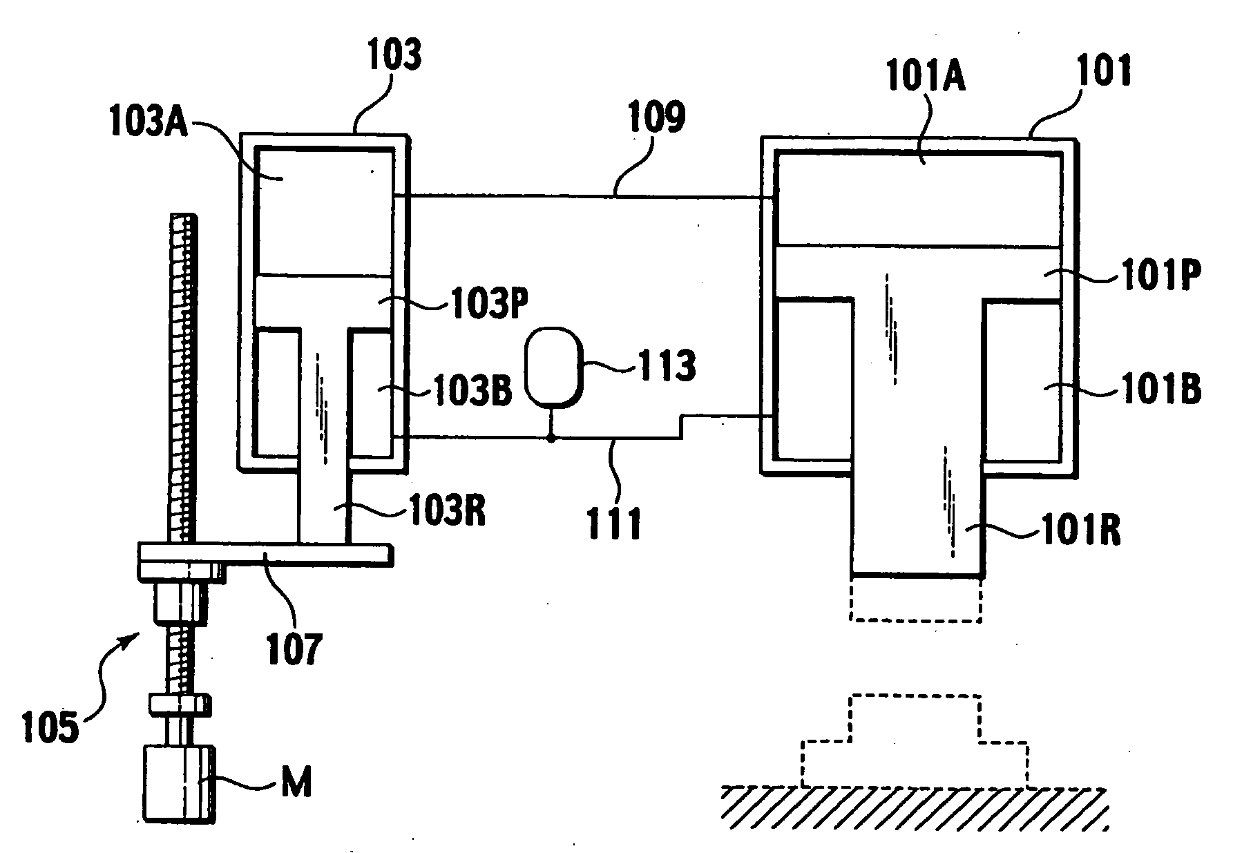
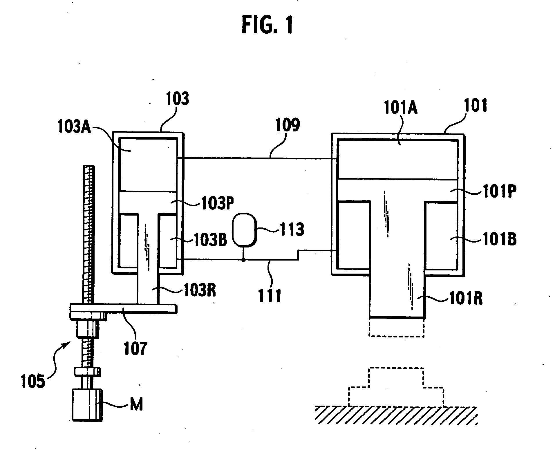
Accordingly, if the large-diameter cylinder 101 is selected by, for example, a pressurization capability or the like of the press machine, the small-diameter cylinder 103 is decided uniquely to correspond to the large-diameter cylinder 101, thus disadvantageously restricting a degree of freedom for design.
Due to this, to make a stroke length of the large-diameter piston rod 101R large, it is disadvantageously necessary to increase a length of the small-diameter cylinder 103.
Besides, if the large-diameter piston rod 101R is to move at high velocity, the velocity of the large-diameter piston rod 101R cannot be set almost equal to a moving velocity of the small-diameter piston rod 103R, thereby hampering improvement in efficiency by high-velocity movement of the ram.
Due to this, to make power of the large-piston rod 101R large, it takes a relatively long time to raise an internal pressure of the first compartment 101A of the large-diameter cylinder 101 to a desired pressure, thereby disadvantageously hampering the improvement in efficiency.
However, if it is configured so that the large-diameter piston rod 101R is fixed to the fixing unit and the large-diameter cylinder 101 is moved relative to the fixing unit, a position of the large-diameter cylinder 101 cannot be detected accurately only by detecting a rotation of the motor M. Therefore, a problem occurs that an expensive linear sensor or the like needs to be arranged between the fixing unit and the large-diameter cylinder 101.

Method used


Image

  • Ram position detection method, ram drive method, ram drive device, and press machine having the ram drive device
  • Ram position detection method, ram drive method, ram drive device, and press machine having the ram drive device
  • Ram position detection method, ram drive method, ram drive device, and press machine having the ram drive device

Examples


second embodiment

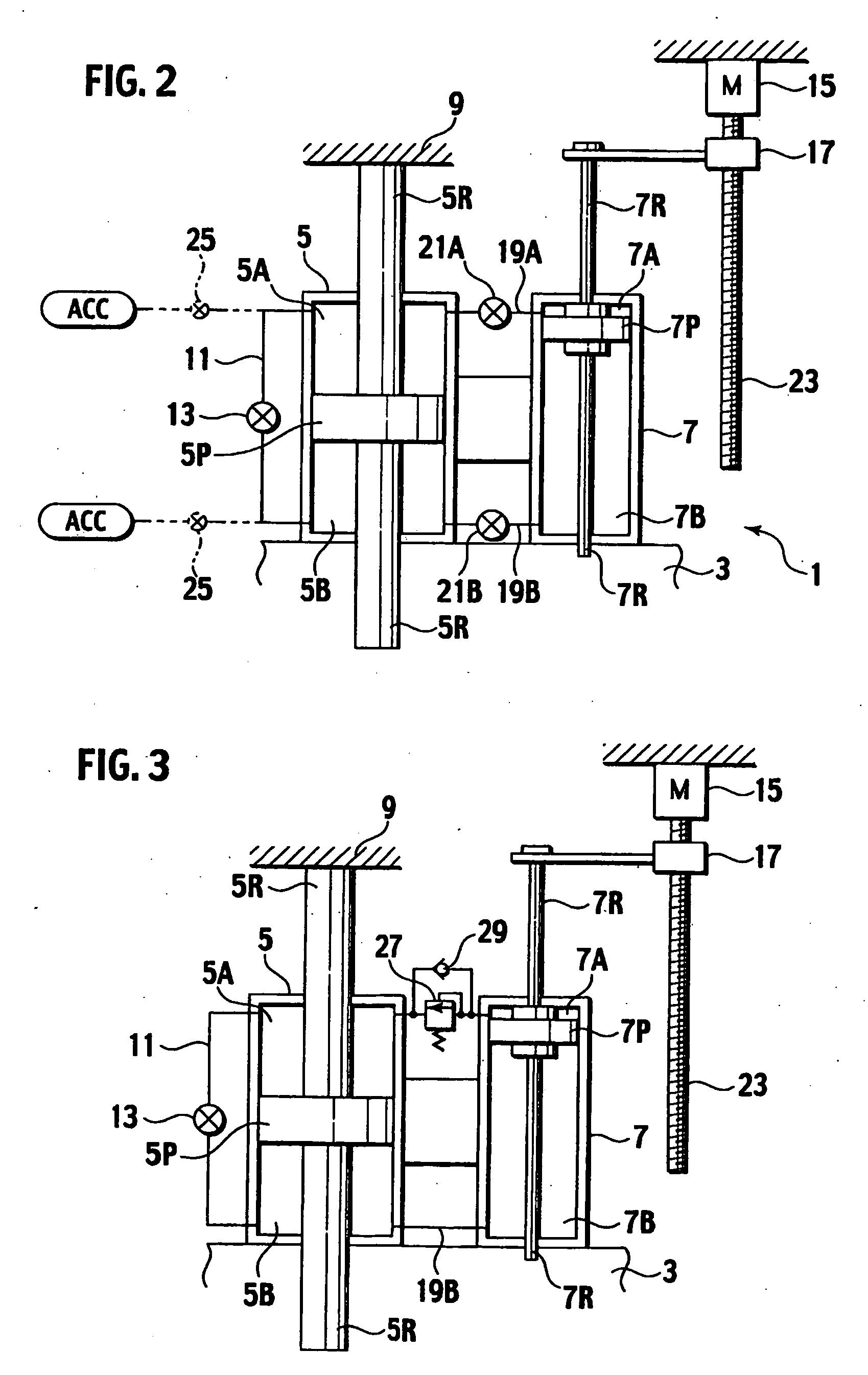
[0056]FIG. 3 shows a second embodiment Constituent elements identical in function to those according to the above embodiment are denoted by like reference symbols and therefore redundant descriptions thereof will be omitted.

[0057]In the second embodiment, a press machine is configured to include a relief valve or counterbalance valve 27 on a part of the connection path 19A to permit the working fluid to flow from the first compartment 7A of the small-diameter cylinder 7 into the first compartment 5A of the large-diameter cylinder 5 when a fluid pressure in the first compartment 7A of the small-diameter cylinder 7 is equal to or higher than a pressure corresponding to the weight of the ram 3 or the like, and to include a check valve 29 arranged in parallel to the counterbalance valve 27 to permit inflow of the working fluid from the first compartment 5A into the first compartment 7A but prevent back-flow of the working fluid. Further, the press machine is configured not to include th...

third embodiment

[0061]FIG. 4 shows a third embodiment Constituent elements identical in function to those according to the above embodiments are denoted by like reference symbols and therefore redundant descriptions thereof will be omitted

[0062]In the third embodiment, the large and small cylinders 5 and 7 provided integrally are connected to the moving member 17 integrally and the small-diameter piston rod 7R of the small-diameter cylinder 7 is fixed to the fixing unit 9. Furthermore, the press machine is configured so that the ram 3 is provided integrally with the large-diameter piston rod 5R of the large-diameter cylinder 5 and so that the first compartment 7A and the second compartment 7B of the small-diameter cylinder 7 are connected to each other by the connection path 11.

[0063]With the above-described configuration, if the motor 15 is driven and the ball screw 23 is rotated while the on-off valve 13 provided on the connection path 11 is kept open and the switch valves 21A and 21B are kept cl...

fourth embodiment

[0067]FIG. 5 shows a fourth embodiment Constituent elements identical in function to those according to the above embodiments are denoted by like reference symbols and therefore redundant descriptions thereof will be omitted.

[0068]The fourth embodiment is a modified embodiment of the first embodiment described above. A diameter of a piston rod 5L on the second compartment 5B side is made larger than that of a piston rod 5S on the first compartment 5A side in the large-diameter cylinder 5, and the pressure reception area of the first compartment 5A side is made larger man that of the second compartment 5B side on the piston 5P. Further, the press machine is configured so that a pressure accumulated in the accumulator ACC always acts on the first compartment 5A

[0069]With the above-described configuration, if the on-off valve 13 is kept open, the pressure accumulated in the accumulator ACC acts on the first and second compartments 5A and 5B of the large-diameter cylinder 5. Due to this...


PUM


Abstract

A ram driving method including the steps of fixing one end of a large-diameter piston rod (5R) integral with a large-diameter piston (5P) reciprocably included in a large-diameter cylinder (5) attached integrally to a ram (3) to a fixing unit (9), connecting one end of a small-diameter piston rod (7R) integral with a small-diameter piston (7P) reciprocably included in a small-diameter cylinder (7) integral with the large-diameter cylinder to a moving member (17) moved by a motor driving, integrally moving the small-diameter cylinder and the small-diameter piston and communicating a first compartment (5A) and a second compartment (5B) of the large-diameter cylinder divided by the large-diameter piston with each other, moving the ram integrally with the small-diameter piston rod moved by the moving member, and communicating the small-diameter cylinder with the large-diameter cylinder, thereby moving the large-diameter cylinder with a strong force by a working fluid supplied from the small-diameter cylinder.

Description

TECHNICAL FIELD[0001]The present invention relates to a ram position detection method, a ram driving apparatus, and a press machine including the ram driving apparatus for a press machine (pressurizer) including a reciprocable ram, such as a press brake. More specifically, the present invention relates to a ram position detection method, a ram driving method, a ram driving apparatus, and a press machine including the ram driving apparatus capable of moving the ram at high velocity using a mechanical configuration and pressing a target by fluid pressure at low velocity at high pressing force when the ram performs a pressurization operation.BACKGROUND ART[0002]As a configuration for driving a ram (slider) movable by a fluid pressure machine, a configuration for reciprocally driving a ram, a table or the like that is one example of a slide is adopted in a press machine (pressurizer) of various types, and a configuration for reciprocating a moving member of various types is adopted in a...

Claims


Application Information

Patent Timeline
Patent Type & Authority Applications(United States)
IPC IPC(8): B30B13/00B30B1/32
CPCF15B7/00B30B1/32
Inventor AOKI, MAKOTOMIZUSHIMA, HIROYUKIARIJI, NOBUAKINOGUCHI, SHIGEKI
Owner AMADA CO LTD
Learn More