
Control of an Exhaust Gas Aftertreatment Device in a Hybrid Vehicle

a technology of exhaust gas aftertreatment and hybrid vehicles, which is applied in the direction of exhaust treatment electric control, electrical control, machines/engines, etc., can solve the problems of low efficiency of hc and nox emission processing, catalyst converter temperature falling below the activation temperature, and inability to fully exhibit the converting effect of catalyst converters, so as to reduce hybrid vehicle emissions and avoid high emissions upon engine restart

Active Publication Date: 2009-01-29
VOLVO CAR CORP
View PDF89 Cites 72 Cited by
  • Summary
  • Abstract
  • Description
  • Claims
  • Application Information

AI Technical Summary

Benefits of technology

[0015]It is an advantage of the present invention that the hybrid vehicle emission are reduced by maintaining an activation temperature in the exhaust gas aftertreatment device even when the engine is not operating. By doing so, high emissions upon engine restart are avoided.
[0016]Below, the invention will be described in detail with reference to the drawings, in which
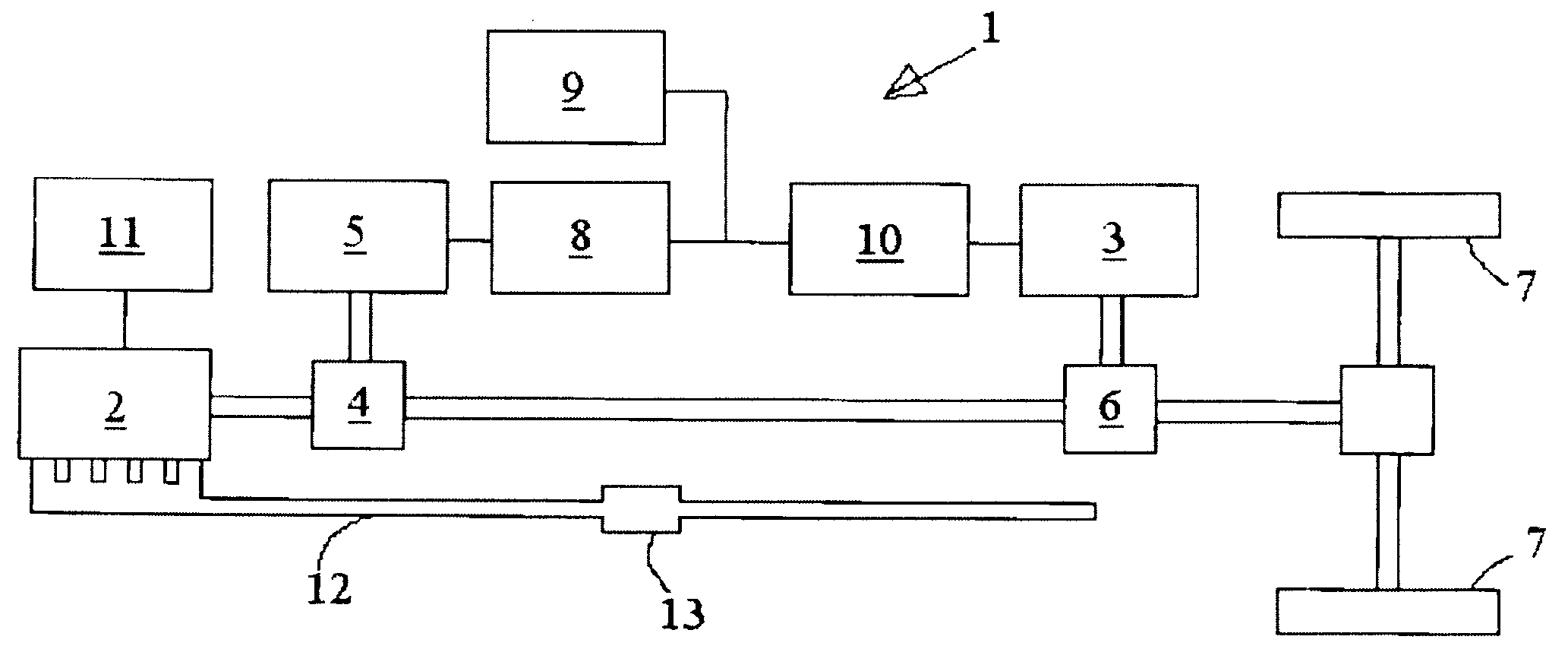
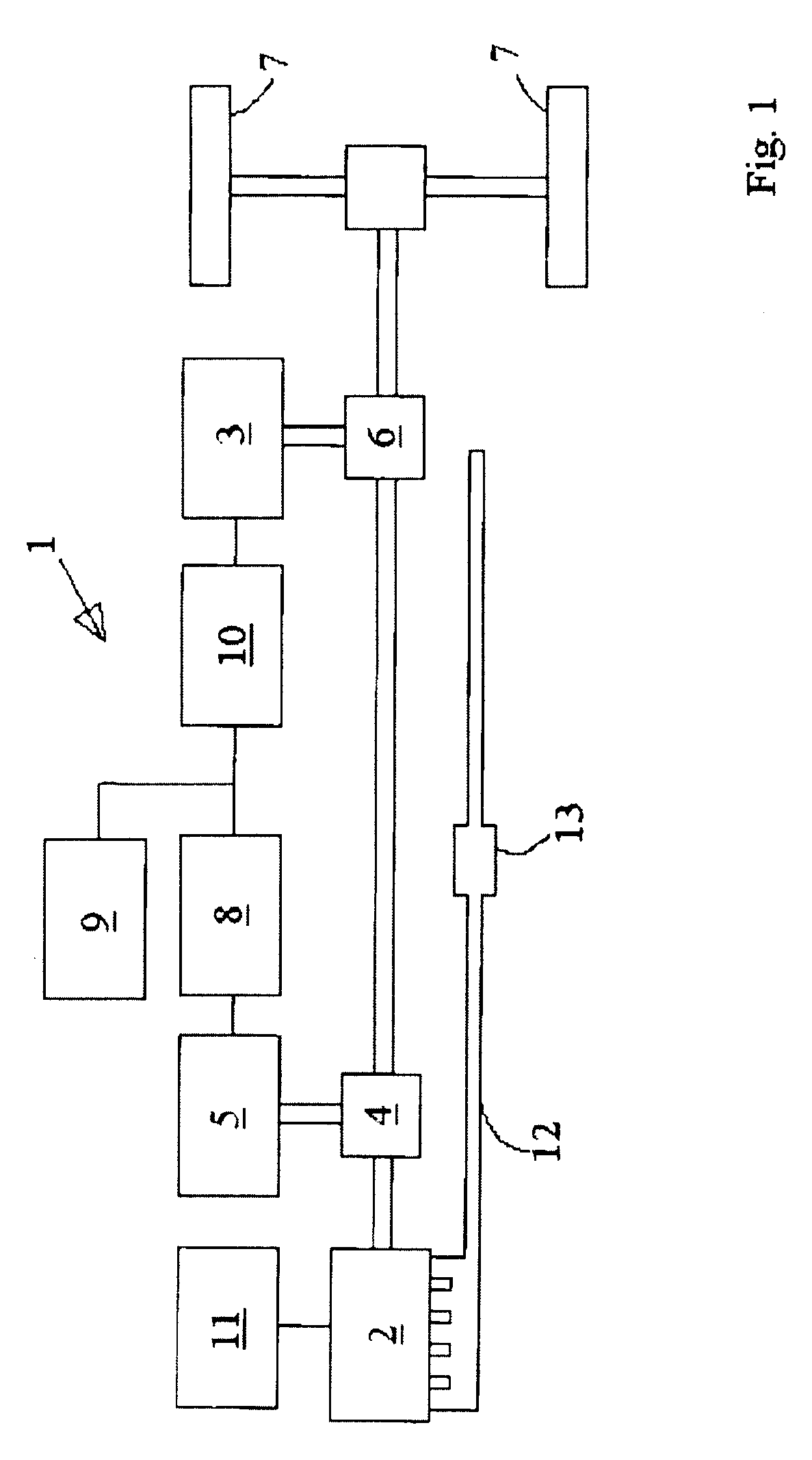
[0017]FIG. 1 shows a schematic view of a hybrid vehicle propulsion system with a combined hybrid structure,
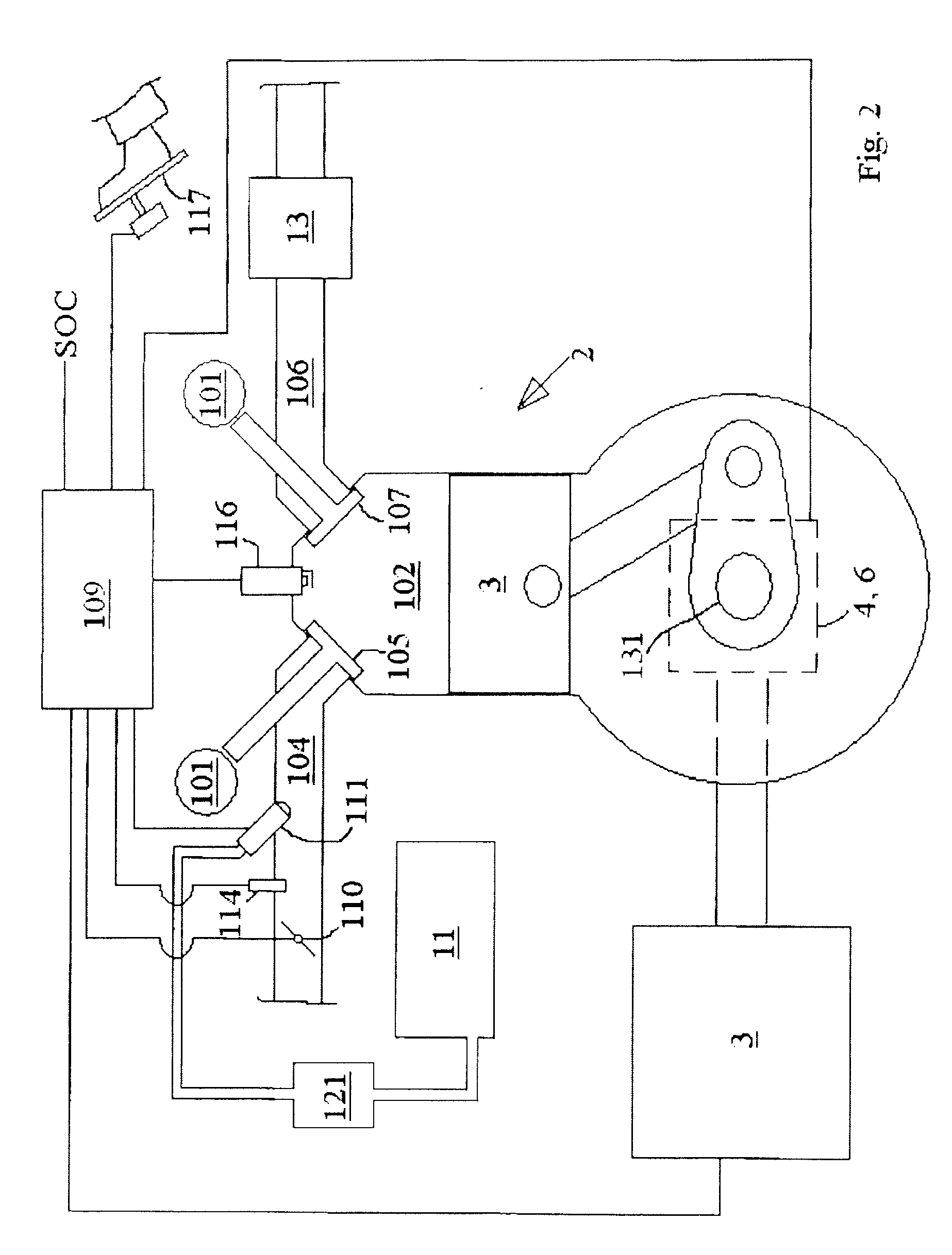
[0018]FIG. 2 shows schematically certain of the hybrid vehicle propulsion system components in FIG. 1 in some detail,
[0019]FIG. 3 shows a block diagram depicting a method according to a preferred

Problems solved by technology

A catalytic converter can not fully exhibit its converting effects when its temperature is lower than its activation temperature.
A problem with hybrid vehicles is that during engine off modes, the catalyst converter temperature can fall below the activation temperature, in which case HC and NOx emission are not efficiently processed in the exhaust gas aftertreatment devices when the internal combustion engine is started again.
However, none of these references describe hybrid vehicles.
However, none of these references describe maintaining catalyst temperature during an engine off mode.

Method used


Image

  • Control of an Exhaust Gas Aftertreatment Device in a Hybrid Vehicle
  • Control of an Exhaust Gas Aftertreatment Device in a Hybrid Vehicle
  • Control of an Exhaust Gas Aftertreatment Device in a Hybrid Vehicle

Examples


Embodiment Construction

[0028]FIG. 1 shows parts of a hybrid vehicle propulsion system 1 with a combined hybrid structure, the propulsion system 1 having an internal combustion engine 2 and an additional power source 3 in the form of an electric motor 3. A first transmission 4 provides in a manner known in the art a mechanical connection between the engine 2, a generator 5 and a second transmission 6, which in turn provides a mechanical connection between the engine 2 via the first transmission 4, the motor 3 and two wheels 7 of the vehicle. The generator 5 is electrically connected to a charger 8, which in turn is connected to an energy storage unit 9 comprising a plurality of batteries, and to a converter 10, the latter being connected to the motor 3. Fuel storage tank 11 comprising a fuel tank 11, and an exhaust system 12 with an exhaust treatment device 13 in the form of a catalytic converter 13 are provided for the engine 2.

[0029]Transmissions 4, 6 are controllable as described below and work as power...


PUM


Abstract

The present invention involves a method for maintaining temperature in an exhaust gas treatment device for an internal combustion engine in a hybrid vehicle. The engine has a crankshaft and at least one cylinder. The hybrid vehicle has a fuel storage device and a fuel supply device. An exhaust gas treatment device is located downstream of the cylinder. The method comprises, in an engine off mode, pumping air to the exhaust gas aftertreatment device controlling the fuel supply device so that fuel is allowed to the exhaust gas aftertreatment device. Air flow to the exhaust gas aftertreatment device can be controlled by a throttle in an inlet duct to the engine and / or the fuel supply device to control the combustion and air-fuel ratio in the exhaust gas treatment device.

Description

TECHNICAL FIELD[0001]The present invention relates to a hybrid vehicle, a hybrid vehicle propulsion system, and a method for an exhaust gas aftertreatment device for an internal combustion engine in a hybrid vehicle further having an additional power source. The internal combustion engine has a crankshaft and at least one cylinder, the hybrid vehicle further comprising fuel storage device and fuel supply device, the exhaust gas treatment device located downstream of the cylinder.BACKGROUND[0002]The drivetrain of a hybrid vehicle includes two combined power sources for the propulsion of the vehicle. Usually an internal combustion engine is combined with an additional power source connected to or including an energy storage unit which can be charged by the internal combustion engine, and, in many solutions, also by recovering the braking energy of the vehicle.[0003]In so called hybrid electric vehicles, the additional power source is typically an electric motor connected to an energy ...

Claims


Application Information

Patent Timeline
Patent Type & Authority Applications(United States)
IPC IPC(8): F01N9/00B60L50/15B60L50/16
CPCB60K6/445Y02T10/6239B60L2240/445B60W10/06B60W10/08B60W10/30B60W20/00B60W2510/068B60W2710/0605B60W2710/0616F01N3/20F01N3/2033F01N3/22F02D41/025F02D41/123Y02T10/54Y02T10/6221Y02T10/6286Y02T10/26B60K6/48Y02T10/12Y02T10/40Y02T10/62Y02A50/20B60W2710/0688B60W2710/088
Inventor HERMANSSON, JONASJOHNSSON, ANDERS HOLGERVOLLMER, NIKLAS
Owner VOLVO CAR CORP
Learn More