
Radiant convection oven

Active Publication Date: 2009-01-15
DURR SYST INC
View PDF23 Cites 26 Cited by
  • Summary
  • Abstract
  • Description
  • Claims
  • Application Information

AI Technical Summary

Benefits of technology

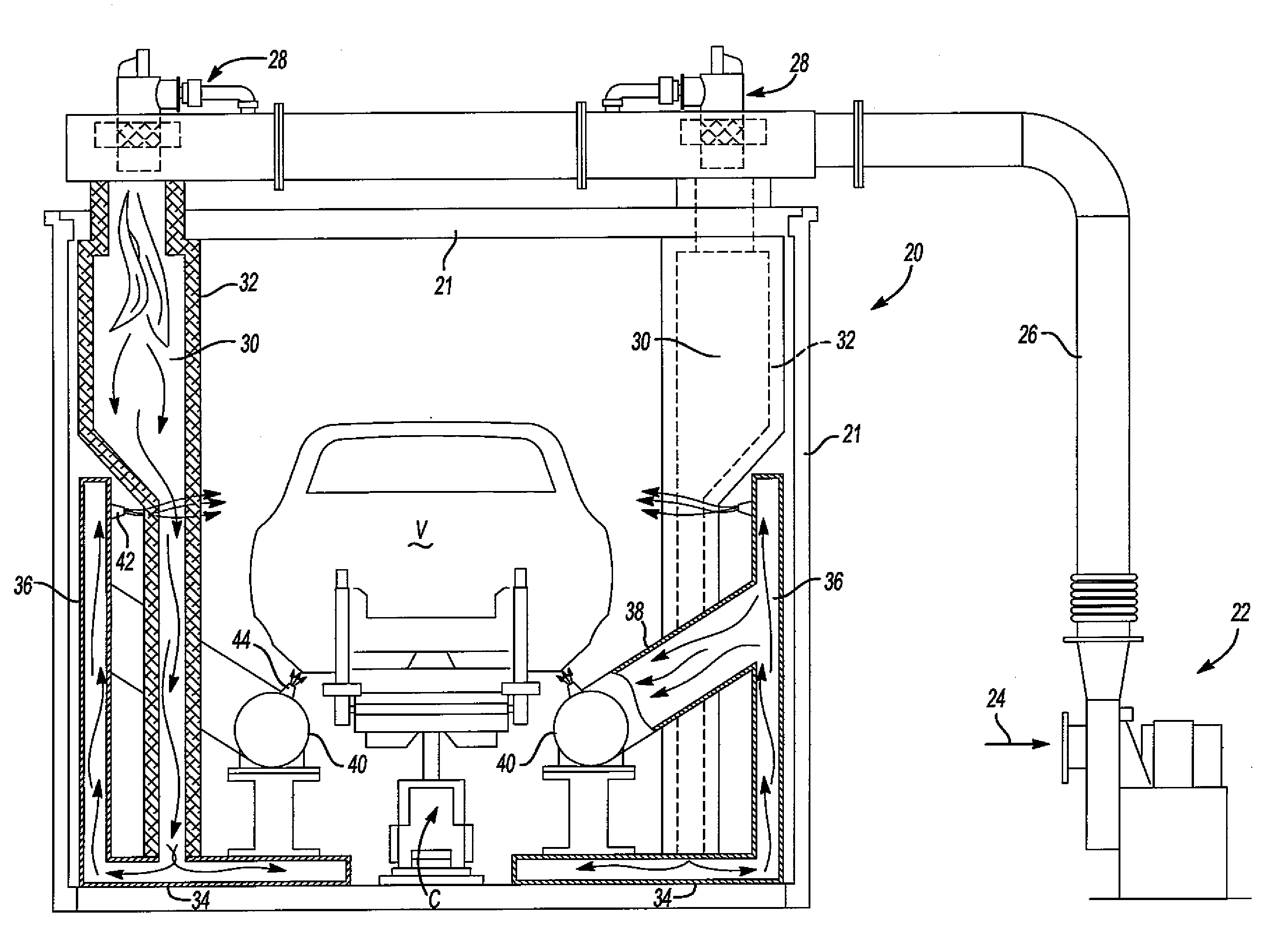
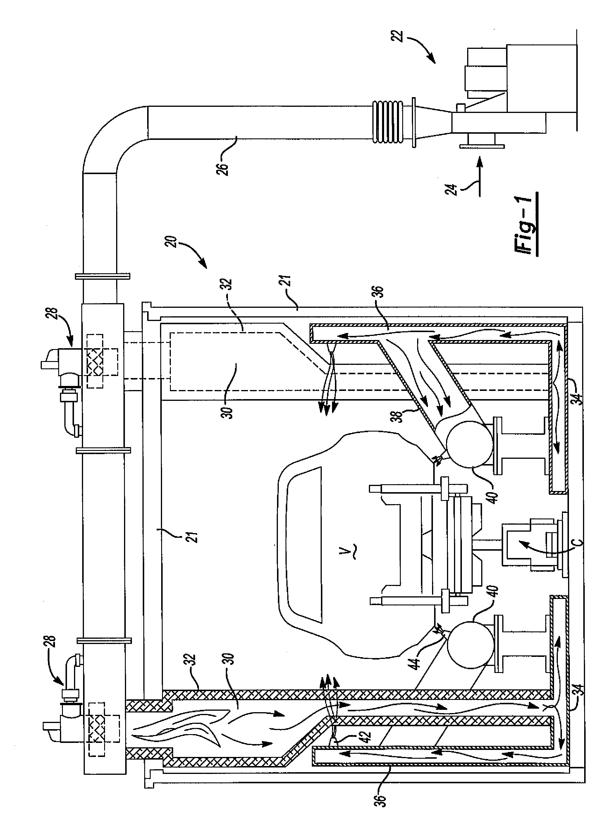
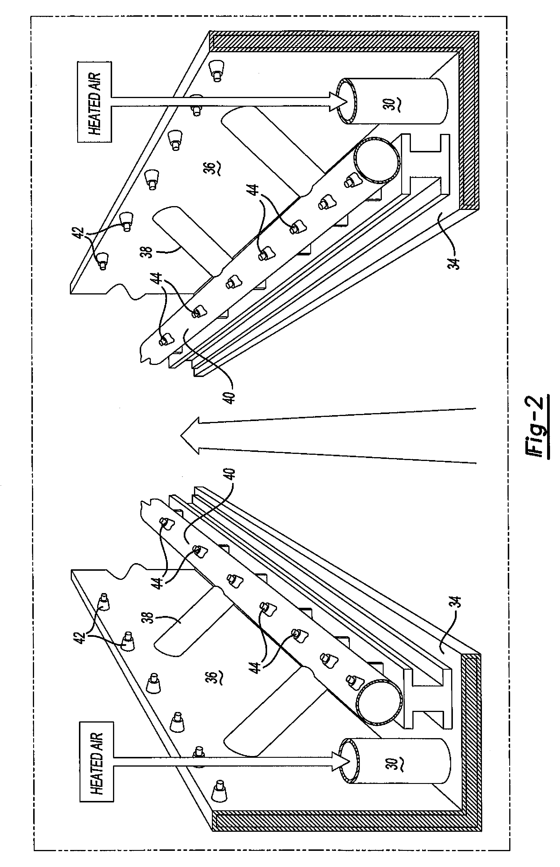
[0010]In the disclosed embodiment of the radiant convection oven of this invention, the internal chamber of the radiating walls has a depth of less than five inches and an air velocity of greater than two thousand feet per minute. More preferably, the velocity of the air through the internal chamber of the radiating walls has a velocity of greater than two thousand five hundred feet per minute and may exceed three thousand feet per minute and the depth of the radiating walls or radiator may be three to five inches or less, significantly reducing the requirement for fresh make-up air while maintaining radiation heat delivered to the coated article equal to conventional radiant bake ovens. Further, in the disclosed embodiment, the internal chamber of the radiating walls have an air volume flow rate of less than five thousand cubic feet per minute. In the disclosed embodiment of the radiant convection oven of this invention, the burner is located outside of the oven enclosure, preferably adjacent or attached to the oven enclosure, and the oven includes a combustion chamber located within the oven receiving hot combustion gas from the burner. In the enclosed embodiment, the radiant convection oven includes two burners, including a burner located adjacent each side wall of the enclosure and the radiating walls include a bottom wall and radiating sidewalls on opposed sides of the oven. Further, the disclosed embodiment of the convection radiant oven of this invention includes radiant ducts on opposed sides of the oven, adjacent the sill area of the vehicle body, receiving hot fresh air from the radiating side walls, directing hot convection air onto the coated article, such as the sill area of a coated vehicle body.

Problems solved by technology

The door sill area is typically made from multiple layers of thicker material, such as steel, and the radiant heating alone is not sufficient to properly heat this area.
It is also possible to allow fresh air to leak into the oven without heating; but this is generally not done because (1) it can lead to condensation problems when the cold air mixes with the hot air inside the oven, and (2) may carry dirt into the oven which would contaminate the coated article.

Method used


Image

  • Radiant convection oven
  • Radiant convection oven
  • Radiant convection oven

Examples


Embodiment Construction

[0014]As set forth above, the radiant convection oven of this invention utilizes fresh air make-up to transfer heat to the coated object. The fresh air make-up is used to the heat radiators and is then delivered to the oven by the radiators as convection air. In the disclosed embodiment, the fresh air is heated by burners mounted to the oven enclosure instead of a separate heater box. The radiant convection oven of this invention may be used for baking or curing any coating on an object, including but not limited to decorative and protective coatings and adhesives as used, for example, by the automotive industry. Although the radiant convection bake oven of this invention may be utilized for any application, it is particularly useful for mass production applications, such as utilized by the automotive industry to cure paint and adhesives on an automotive body. In order for the radiant convection oven of this invention to heat a coated object at the same rate as a conventional radian...


PUM


Abstract

A radiant convection oven for baking a coating on an article which includes an oven enclosure receiving coating articles, a fan receiving fresh air and directing the fresh air to a burner or burners, a plurality of heat radiators each having an internal chamber receiving heated fresh air from the burner. The radiators are located within the oven opposite a coating article, radiating heat energy to the coated article, and a plurality of nozzles connected to the internal chamber of the radiators directing fresh heated onto the article, transferring convection heat energy to the coated article. In the disclosed embodiment, the radiators include radiating side and bottom walls having a relatively shallow depth, increasing the flow rate through the radiators, reducing the size and cost of the radiators and the fan.

Description

RELATED APPLICATIONS[0001]This non-provisional patent application claims priority to a provisional patent application Ser. No. 60 / 995,542, filed on Sep. 27, 2007 and is a continuation-in-part application of Ser. No. 11 / 701,254 filed on Feb. 1, 2007, which application claims priority to provisional application Ser. Nos. 60 / 814,632, filed Jun. 16, 2006 and 60 / 807,875, filed Jul. 20, 2006 and 60 / 839,082, filed Aug. 21, 2006.FIELD OF THE INVENTION[0002]This invention relates to a radiant convection oven for baking or curing a coating on an article. As used herein, the term “baking” is defined as heating an object or article for the purpose of drying or curing the coating, including paint. Paint is defined as a decorative, protective or performance enhancing coating or sealant.BACKGROUND OF THE INVENTION[0003]A paint bake oven typically includes an oven enclosure into which coated articles are received, typically on a conveyor, a heating system to provide heat for drying or curing the co...

Claims


Application Information

Patent Timeline
IPC IPC(8): F26B3/04F26B3/30
CPCB05D3/0254B05D3/0413B05D7/14F26B3/283F27B9/36F26B21/004F26B2210/12F27B9/10F26B3/305
Inventor PAKKALA, JAMES L.KLOBUCAR, JOSEPH M.YU, GUANG
Owner DURR SYST INC
Learn More