
Processing device

a processing device and single-wallet technology, applied in the direction of manufacturing tools, transportation and packaging, coatings, etc., can solve the problems of inability to uniformly exhaust gas from around the mounting table, the change in gas exhaust conductance relative to the change in the valve opening degree is too small or too great to stably control the pressure, and the deviation in gas flow. , to achieve the effect of increasing the uniformity of in-plane gas

Inactive Publication Date: 2009-01-08
TOKYO ELECTRON LTD
View PDF2 Cites 29 Cited by
  • Summary
  • Abstract
  • Description
  • Claims
  • Application Information

AI Technical Summary

Benefits of technology

The present invention provides a processing apparatus that can exhaust the ambient gas in a uniform manner around a mounting table when the valve opening degree varies within a practical use region. This is achieved by arranging a pressure control valve in a gas exhaust port eccentrically from the center axis of the mounting table. This results in increased in-plane uniformity when processing the target object. The gas exhaust system includes a turbo molecular pump and the mounting table can be supported by a sidewall of the processing chamber or through support legs.

Problems solved by technology

However, if the valve opening degree is small as is the case in an actual process, there occurs a deviation in the gas flow.
Stating differently, if the processing apparatus is designed to control the process pressure with an excessively small valve opening degree or an excessively high valve opening degree, the change in gas exhaust conductance relative to the change in the valve opening degree is too small or too great to stably control the pressure.
As a consequence, it becomes impossible to uniformly exhaust the gas from around the mounting table 6.
This poses a problem in that the in-plane uniformity is reduced when processing a wafer.
This problem becomes conspicuous as the size of a gas exhaust port grows larger together with the increase in the wafer size to 300 mm and the resultant increase in the size of the processing chamber 4.

Method used


Image

  • Processing device
  • Processing device
  • Processing device

Examples


Embodiment Construction

[0037]Hereinafter, one embodiment of a processing apparatus in accordance with the present invention will be described with reference to the accompanying drawings.

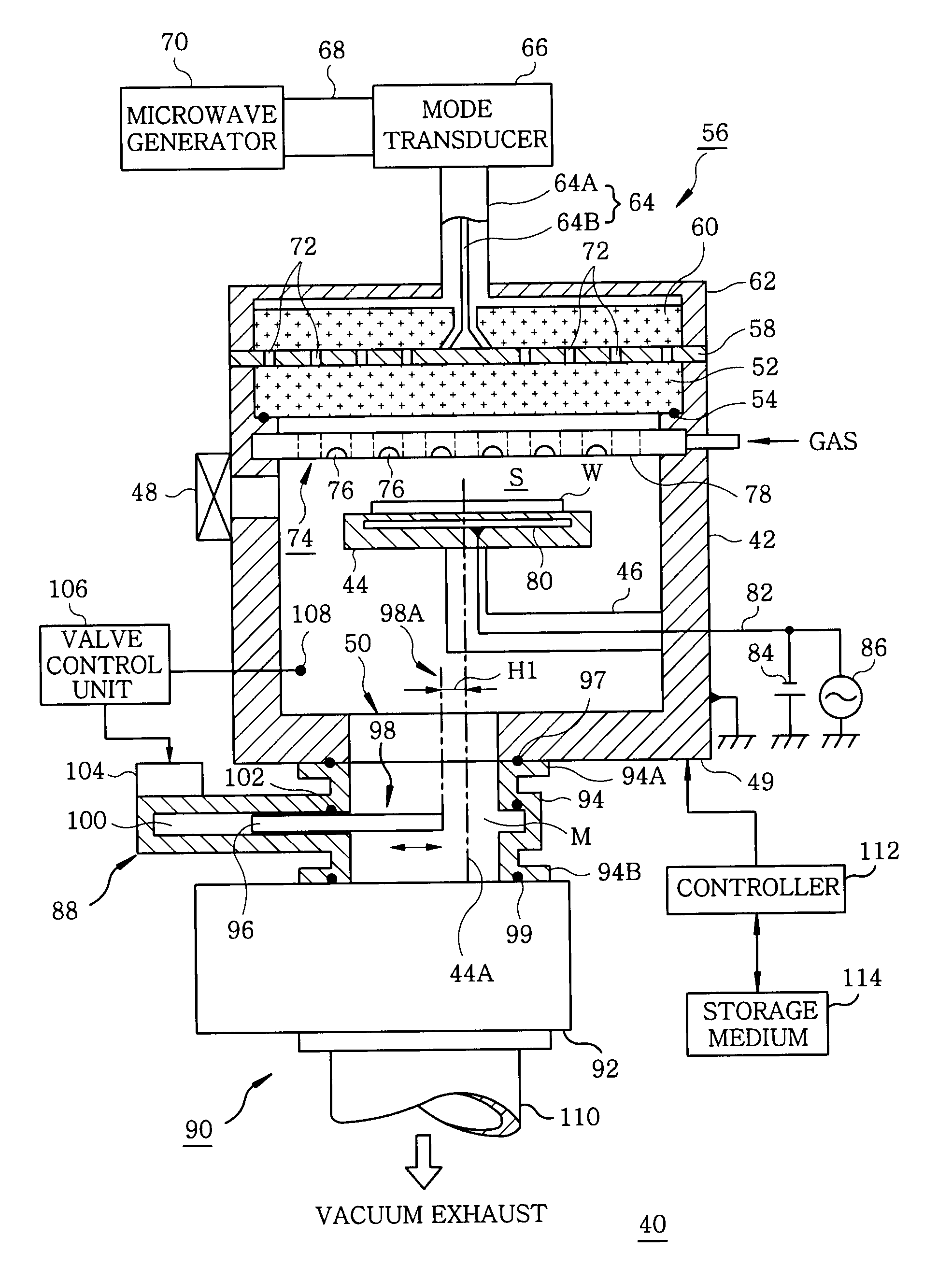
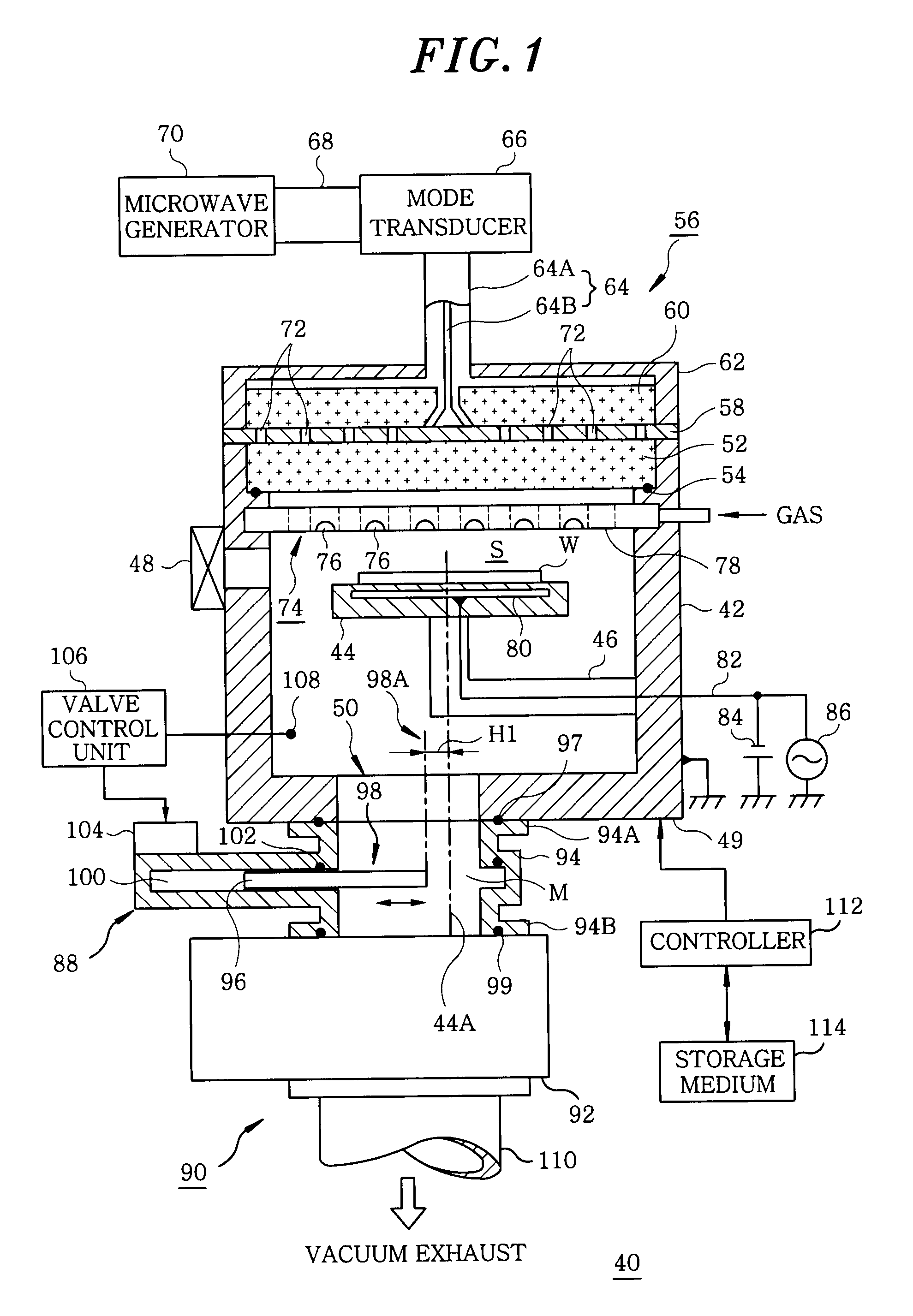
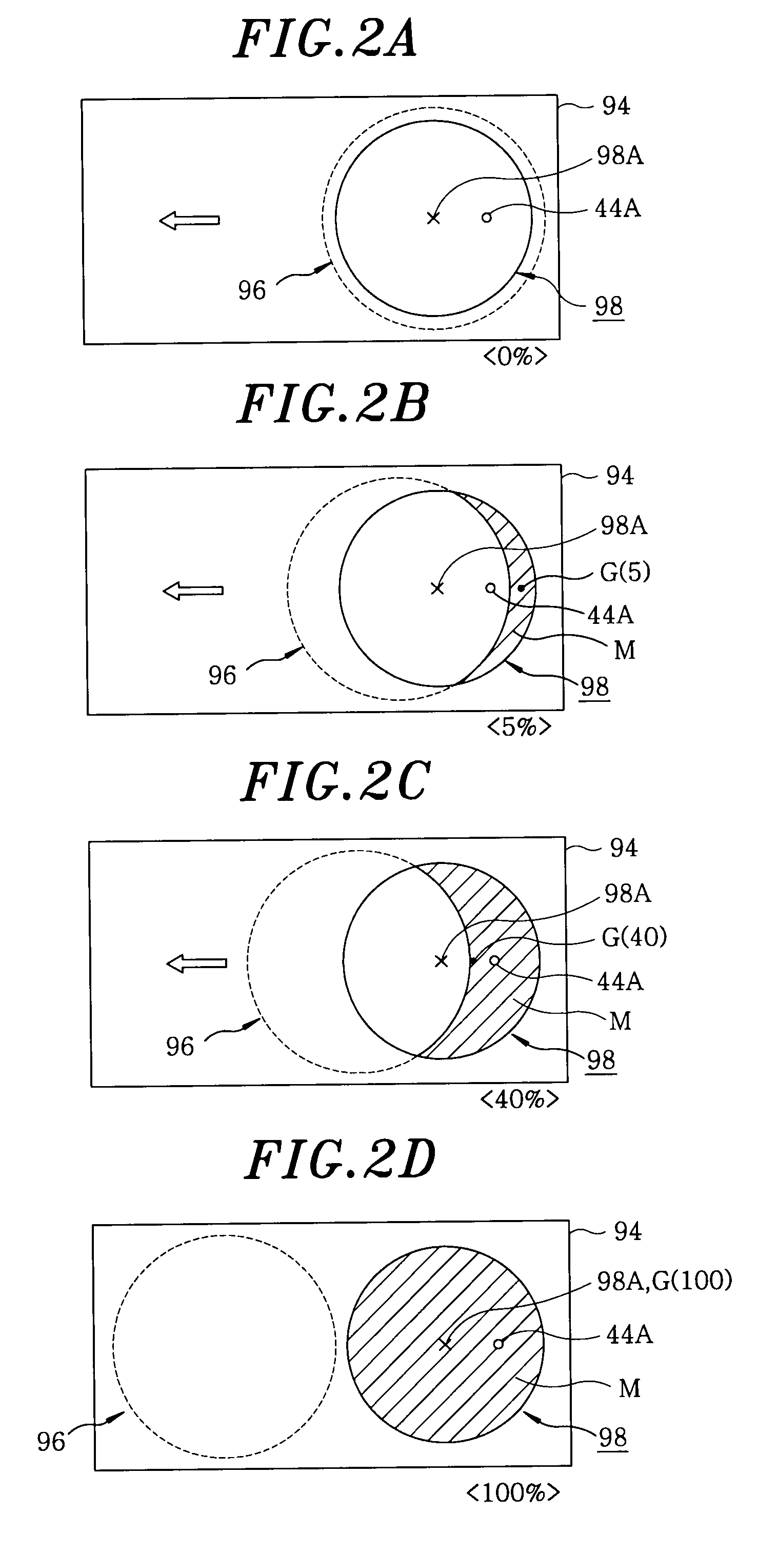
[0038]FIG. 1 is a configuration view showing one example of a processing apparatus in accordance with the present invention. FIGS. 2A to 2D are views explaining the change in a valve opening degree of a pressure control valve. FIG. 3 is a plan view illustrating one example of the movement trajectory of a gravity center of the plane defined by an opening region. FIG. 4 is a schematic view illustrating the flow of an exhaust gas in the processing apparatus of the present invention. FIGS. 5A and 5B are graphs representing the relationship between the valve opening degree of the pressure control valve and a pressure within a processing chamber and the relationship between the valve opening degree of the pressure control valve and an exhaust conductance. A plasma processing apparatus will be described herein as an example of th...


PUM

PropertyMeasurementUnit
sizeaaaaaaaaaa
thicknessaaaaaaaaaa
frequencyaaaaaaaaaa

Abstract

In a processing apparatus for performing a specified process on a target object at a predetermined process pressure, the apparatus includes an evacuable processing chamber having a gas exhaust port formed in a bottom portion thereof; a mounting table provided within the processing chamber for holding the target object; a pressure control valve connected to the gas exhaust port, the pressure control valve including a slide-type valve body for changing an area of an opening region of a valve port; and a gas exhaust system connected to the pressure control valve. The pressure control valve is eccentrically arranged such that a center axis of the mounting table lies within an opening region of the pressure control valve formed over a practical use region of a valve opening degree of the pressure control valve.

Description

FIELD OF THE INVENTION[0001]The present invention relates to a single wafer plasma processing apparatus for use in performing various kinds of processes, such as plasma processing, film-forming and etching, on semiconductor wafers or the like sheet by sheet.BACKGROUND OF THE INVENTION[0002]In order to manufacture semiconductor products such as a semiconductor integrated circuit and the like, it is general that a semiconductor wafer is repeatedly subjected to various kinds of processes, including film-forming, etching, oxidizing and diffusing, ashing and reforming. As the semiconductor products become highly dense and miniaturized, the various kinds of processes need to be performed with high in-plane uniformity in view of the improvement of a product yield rate.[0003]In this regard, a plasma processing apparatus will be described as an example of the conventional single wafer plasma processing apparatus. Plasma processing apparatuses are disclosed in, e.g., Japanese Patent Laid-open...

Claims


Application Information

Patent Timeline
Patent Type & Authority Applications(United States)
IPC IPC(8): B23K9/00
CPCC23C16/4412C23C16/511H01L21/67126H01J37/32834H01L21/67017C23C16/52Y10T137/85978
Inventor NOZAWA, TOSHIHISAYUASA, TAMAKI
Owner TOKYO ELECTRON LTD
Learn More