
Walking Assistance Device

a technology of assistance device and free leg, which is applied in the direction of walking aids, non-surgical orthopedic devices, physical therapy, etc., can solve the problems of increasing the cost disadvantageously, affecting the alleviation effect of user's constraint feeling, forward or backward pushing force applied to the load transfer portion, etc., to improve the stability of the walking assistance device, alleviate the load applied to the user's free leg due to the moment of inertia of the leg link, and the load applied to the user's

Active Publication Date: 2008-12-25
HONDA MOTOR CO LTD
View PDF4 Cites 7 Cited by
  • Summary
  • Abstract
  • Description
  • Claims
  • Application Information

AI Technical Summary

Benefits of technology

[0009]The present invention has been accomplished in view of the aforementioned problems, and it is therefore an objective of the present invention to provide a walking assistance device which improves stability by preventing a pushing force in the anteroposterior direction from being applied to a load transfer portion in a state where a user stands upright, regardless of a drive source for a third joint portion of a leg link and a battery for the drive source are equipped thereon, and curtails the moment of inertia of the leg link by alleviating a load applied to the user's leg.
[0012]According to the first aspect of the present invention, since the frontal plane passing through the second joint portion lies in the anteroposterior widths of the drive source and the battery in the state where the user stands upright, an anteroposterior offset distance of the center of gravity of each of the drive source and battery with respect to the frontal plane become shorter. Accordingly, the anteroposterior tilting moment which centers at the second joint portion and is generated according to the weights of the drive source and the battery and is applied to the leg link becomes smaller. Consequently, in the state where the user stands upright, an anteroposterior pushing force which is generated according to the tilting moment and applied to the load transfer portion becomes smaller, thereby improving the stability of the walking assistance device.
[0013]According to the second aspect of the present invention, the drive source and the battery are disposed at the same height as or higher than the third joint portion, in other words, are disposed close to the first joint portion, thereby making the moment of inertia around the first joint portion of the leg link smaller. Therefore, when the user swings the free leg toward, the load applied to the free leg due to the moment of inertia of the leg link can be alleviated.
[0015]Meanwhile, the load transfer portion may be formed by a harness which is fixed to the user's waist. According to this configuration, the harness must be fixed tightly so as to certainly transfer the force from the leg link to the user's trunk, which thereby impairs the alleviation effect on the constraint feeling of the user. Regarding this problem, by constituting the load transfer portion from a seat member where the user sits astride, the force from the leg link can be transferred absolutely to the user's trunk from the user's crotch via the seat member. Moreover, it is only necessary for the user to sit on the seat member astride to use the walking assistance device; therefore, the constraint feeling on the user is considerably alleviated.
[0016]In this case, it is preferred that the first joint portion includes an arc-shaped guide rail which is longitudinal in an anteroposterior direction and has the center of curvature located above the seat member, and the center of curvature is configured to match the swing fulcrum of the leg link in the anteroposterior direction by movably engaging an upper end of the leg link movably engaged with the guide rail. According to this configuration, in cases where the action point of the weight of the user's upper body is deviated to the front of the swing fulcrum of the leg link in the anteroposterior direction with respect to the seat member, causing the seat member to incline anteroinferiorly, since the swing fulcrum of the leg link in the anteroposterior direction is located above the seat member, the action point of the weight is displaced backward under the swing fulcrum of the leg link in the anteroposterior direction, decreasing an anteroposterior distance between the fulcrum and the action point of the weight, which thereby decreases a rotation moment applied to the seat member. Therefore, the rotation moment applied to the seat member becomes zero when the action point of the weight is displaced to the position beneath the swing fulcrum of the leg link in the anteroposterior direction, which is a stable state for the seat member. Since the seat member automatically converges on the stable state, it is possible to prevent the seat member from deviating in the anteroposterior direction under the user's crotch.
[0017]If the first joint portion is configured to have an arc-shaped guide rail in this way, a space is formed between the underside of the seat member and the guide rail. Therefore, by disposing the battery on the underside of the seat member so as to be housed in the space, the space which would be a dead space between the seat member and the guide rail may be utilized effectively and reasonably.

Problems solved by technology

In addition, it is necessary to provide the drive sources for driving the joint portions such as the hip joint portion, the knee joint portion, and the ankle joint portion, respectively, which increases the cost disadvantageously.
However, this solution resultantly impairs the alleviation effect on the constraint feeling of the user.
However, in the above-mentioned case, since the drive source and the battery are both heavy loads, when the user stands upright, divergence of the center of gravity of the drive source and the battery to either a forward direction or a backward direction with respect to a frontal plane (a plane which is vertical and parallel to a transverse direction) passing through the lower second joint portion of the leg link generates a forward or backward tilt moment to the leg link with respect to the second joint portion as the center, which causes a forward or backward pushing force applied to the load transfer portion.
Further, the moment of inertia around the first joint portion of the leg link may become great according to the disposed height of the drive source and the battery, which thereby increases a load applied to the free leg due to the moment of inertia of the leg link when a free leg of the user (a leg whose foot is off from the ground) swings forward.

Method used


Image

  • Walking Assistance Device
  • Walking Assistance Device
  • Walking Assistance Device

Examples


Embodiment Construction

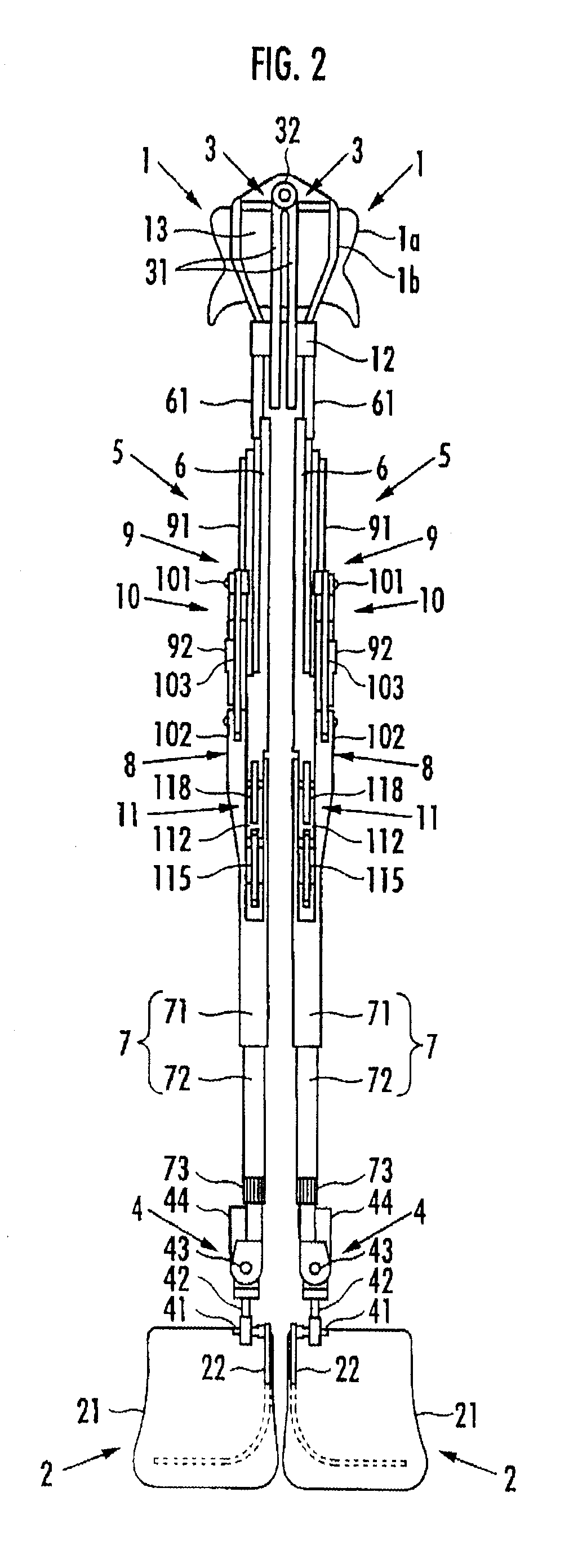
[0022]A walking assistance device according to an embodiment of the present invention will be described hereinafter. As illustrated in FIG. 1 and FIG. 2, the walking assistance device includes a seat member 1 as a load transfer portion on which a user P sits astride, a pair of left and right foot attachment portions 2 and 2 which are attached to user's left and right feet, respectively, and a pair of left and right leg links 5 and 5 which are connected to the seat member 1 each via a first joint portion 3 located at the upper end and connected to the two foot attachment portions 2 and 2 each via a second joint portion 4 located at the lower end.

[0023]Each leg link 5 is composed of a freely bending and stretching link which varies a distance between the first joint portion 3 and the second joint portion 4. More specifically, each leg link 5 includes an upper first link portion 6 connected to the seat member 1 via the first joint portion 3 and a lower second link portion 7 connected t...


PUM


Abstract

A walking assistance device having a leg link connected to a load transfer portion via a first joint and to a foot attachment portion via a second joint, and having an intermediate third joint moving such that a distance between the first joint and the second joint is variable; a drive source for the third joint; and a battery for the drive source. When in an upstanding position, force in the forward-backward direction is prevented from acting on the load transfer portion to enhance stability. Also, a moment of inertia of the leg link is decreased to curtail a load applied to the leg of the user. The drive source and the battery are located at positions higher than the third joint, and when the user is in an upstanding position, a plane passing through the second joint lies between the drive source and the battery.

Description

BACKGROUND OF THE INVENTION[0001]1. Field of the Invention[0002]The present invention relates to a walking assistance device for assisting a user in walking.[0003]2. Description of the Related Art[0004]Conventionally, as a type of walking assistance device, there is known one including a trunk attachment portion which is attached to a user's trunk, a thigh attachment portion which is connected to the trunk attachment portion via a hip joint portion corresponding to a human hip joint and attached to a thigh of a user's leg, a crus attachment portion which is connected to the thigh attachment portion via a knee joint portion corresponding to a human knee joint and attached to the crus of the user's leg, and a foot attachment portion which is connected to the crus attachment portion via an ankle joint portion corresponding to a human ankle joint and attached to a user's foot, wherein a drive source for driving each of the joint portions is provided coaxially with the respective joint p...

Claims


Application Information

Patent Timeline
Patent Type & Authority Applications(United States)
IPC IPC(8): A61H3/00
CPCA61H3/008A61H2201/5061A61H2201/5071A61H3/00A61H2201/0192A61H2201/1215A61H2201/1436A61H2201/1642A61H2201/165A61H2201/1676A61H2201/149
Inventor ASHIHARA, JUNHIKI, YUTAKAKUDOH, HIROSHINODA, TATSUYAIKEUCHI, YASUSHI
Owner HONDA MOTOR CO LTD
Learn More