Method for manufacturing liquid discharge head
a liquid discharge head and manufacturing method technology, applied in the field of liquid discharge head manufacturing, can solve the problems of narrow material options and small particulate substances sticking near the discharge ports, and achieve the effects of reducing ink mist puddles, reducing substances sticking, and good discharging without random droplets
- Summary
- Abstract
- Description
- Claims
- Application Information
AI Technical Summary
Benefits of technology
Problems solved by technology
Method used
Image
Examples
example 1
[0060]First, a substrate 1 on which an electrothermal converter was disposed as an energy generating element 2 was prepared (FIG. 3A).
[0061]A polyether amide resin (HIMAL 1200 of Hitachi Chemical Co., Ltd., N-methyl-2-pyrrolidone and butyl cellosolve acetate were used as solvents) was applied on the substrate 1 (FIG. 3B).
[0062]The substrate 1 was baked at 100° C. for 30 minutes, and then at 250° C. for 60 minutes to form a film with a thickness of 2 μm.
[0063]A photosensitive positive type resist was applied on the polyether amide organic material 6 by spin-coating, and then patterned to form a photosensitive positive type resist pattern. The polyether amide resin was etched by using the photosensitive positive type resist pattern, and then the photosensitive positive type resist was peeled off to form an organic material layer 7 of the patterned resin (FIG. 3C).
[0064]Polymethyl isopropenyl ketone (ODOUR-1010A of Tokyo Ohka Kogyo Co., Ltd., using cyclohexanone as a solvent) was appli...
example 2
[0083]This example was for improving removability of a substance sticking to a discharge port surface.
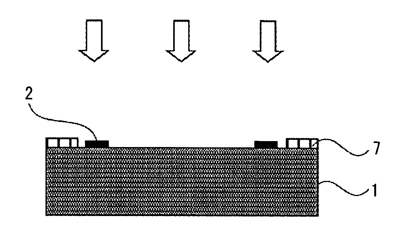
[0084]Processes shown in FIGS. 3A to 3C were similar to those of the Example 1.
[0085]As shown in FIG. 5, an organic material layer 7 formed on a substrate 1 was irradiated with ultraviolet light. The ultraviolet light was irradiated by the full exposure unit (CE-6000) of Ushio, Inc., which can irradiate with the ultraviolet light having short waves of 300 nm or lower. Irradiation time can be calculated by dividing a designated irradiation amount by a total irradiation intensity value. The total irradiation intensity value is a total value of irradiation intensities automatically measured by the apparatus at each wavelength from 220 nm to 320 nm of ultraviolet light.
[0086]Processes thereafter were similar to those of the Example 1.
PUM
| Property | Measurement | Unit |
|---|---|---|
| thickness | aaaaa | aaaaa |
| thickness | aaaaa | aaaaa |
| thickness | aaaaa | aaaaa |
Abstract
Description
Claims
Application Information
 - R&D
- Intellectual Property
- Life Sciences
- Materials
- Tech Scout
- Unparalleled Data Quality
- Higher Quality Content
- 60% Fewer Hallucinations
Browse by: Latest US Patents, China's latest patents, Technical Efficacy Thesaurus, Application Domain, Technology Topic, Popular Technical Reports.
© 2025 PatSnap. All rights reserved.Legal|Privacy policy|Modern Slavery Act Transparency Statement|Sitemap|About US| Contact US: help@patsnap.com


