
Catalytic Conversion Method Of Increasing The Yield Of Lower Olefin

a technology of hydrocarbon oil and conversion method, which is applied in the direction of physical/chemical process catalysts, bulk chemical production, organic chemistry, etc., can solve the problems of reducing the total reducing the profit of the process, and reducing so as to increase the yield of light olefins

Active Publication Date: 2008-12-25
RES INST OF PETROLEUM PROCESSING SINOPEC +1
View PDF24 Cites 17 Cited by
  • Summary
  • Abstract
  • Description
  • Claims
  • Application Information

AI Technical Summary

Benefits of technology

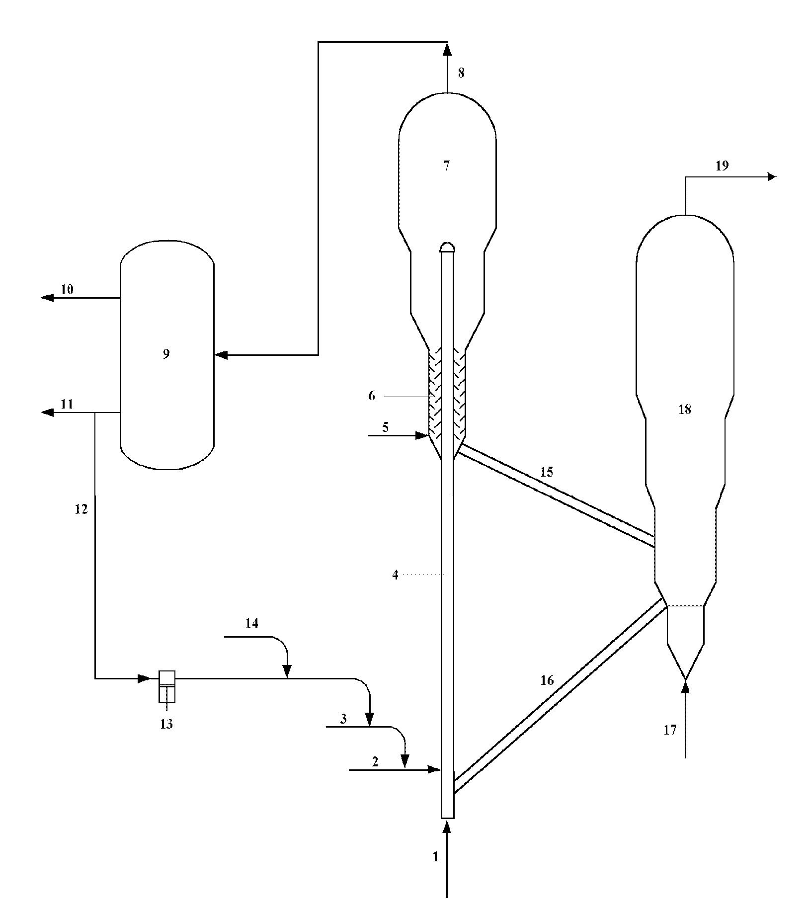
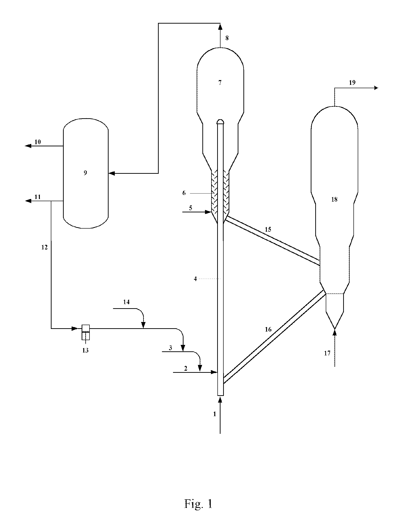
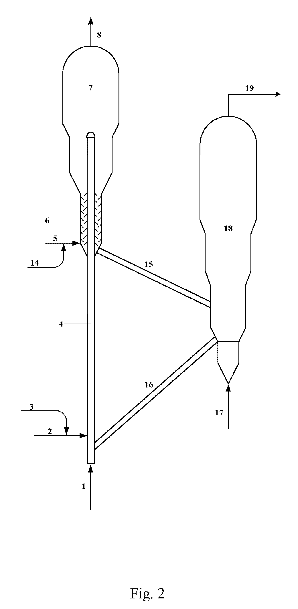
[0008]The object of the present invention is to provide a catalytic conversion process for increasing light olefin yields on the basis of the inventor's discovery. This process will increase light olefin yields, especially propylene yield, by inhibiting the subsequent converting reaction of light olefins such as propylene after their formation with the use of an inhibitor.
[0026]Comparing to the prior art, the present invention possesses the following advantages:
[0027]1. The process of the present invention can weaken the further converting reaction of produced light olefins to 50-70% of the original level by injecting the inhibitor; thereby it can increase the yields of the target products. When vacuum gas oil is used as the feedstock, the yield of ethylene is as high as 8.73 wt % and that of propylene is as high as 29.30 wt %, increasing by 14.4% and 26.6% respectively comparing to those obtained without the inhibitor being injected.
[0028]2. The present invention can reduce the amount of the steam used by injecting the inhibitor into the reactor, and it can further decelerate the hydrothermal deactivation of the catalyst to a certain extent and prolong the service life of the catalyst.

Problems solved by technology

Although the propylene yield can be increased by adequately lowering the reaction severity, the mass ratio of propylene to ethylene is not suitable to exceed 0.65, otherwise, the total yield of light olefins may be decreased and the profit of the process will shrink in consequence.
But the supply amount of light hydrocarbons is limited along with the trend that the crude oil is becoming heavier, so that researchers have to shift their focus to use a wider range of feedstock including heavy petroleum hydrocarbons for producing light olefins.

Method used


Image

  • Catalytic Conversion Method Of Increasing The Yield Of Lower Olefin
  • Catalytic Conversion Method Of Increasing The Yield Of Lower Olefin
  • Catalytic Conversion Method Of Increasing The Yield Of Lower Olefin

Examples


example 1

[0037]This example shows the catalytic reactivity of the light olefin in a bench fixed fluidized bed reactor using carbon monoxide as the inhibitor according to the process of the present invention.

[0038]The experiment was conducted in a batch operation mode with the feedstock A as the feedstock. The feedstock, the inhibitor and the atomizing steam were heated by a preheating furnace to about 350° C. and then fed to the bottom of the fluidized bed reactor via the feed nozzle, coming into contact with the hot catalyst to carry out the catalytic conversion reaction. The reactant vapor and the inhibitor were separated from the coke deposited catalyst and then entered the product separation system, and the reactant vapor was further separated into a gas product and a liquid product. After the reaction was finished, the stripping step was conducted to strip out the hydrocarbon products adsorbed on the spent catalyst by steam. After stripping, an oxygen-containing gas was introduced into ...

example 1 ′

Example 1′

[0039]This example shows the catalytic reactivity of the light olefin in the case of no inhibitor being injected during the reaction, aiming to further demonstrate the practical effect of the present invention. This example has a different experiment phenomenon discovered by the inventors in the laboratory from those as known by the conventional knowledge.

[0040]The feedstock A was used as the feedstock in the experiment. The used reactor, the main experiment steps and other operating conditions were the same as those of Example 1. The main operating conditions and results are listed in Table 2.

[0041]It can be seen from the comparison between the experiment results of Example 1 and Example 1′ in Table 2 that propylene had a considerable high reactivity under the conventional reaction conditions for producing light olefins by the catalytic conversion and the conversion of propylene is as high as 55.19 wt %. This was quite different from the knowledge of most researchers. The...

example 2

[0042]The present example shows the catalytic reactivity of the light olefin in a bench fixed fluidized bed reactor using hydrogen as the inhibitor according to the process of the present invention.

[0043]The feedstock A was used as the feedstock in the experiment. The used reactor and the main experiment steps were the same as those of Example 1. The main operating conditions and results are listed in Table 2.


PUM

PropertyMeasurementUnit
Temperatureaaaaaaaaaa
Timeaaaaaaaaaa

Abstract

A catalytic conversion process for increasing the light olefin yields, which comprises bringing a hydrocarbon oil feedstock into contact with a catalytic conversion catalyst in a catalytic conversion reactor including one or more reaction zones to carry out the reaction, wherein the hydrocarbon oil feedstock is subjected to the catalytic conversion reaction in the presence of an inhibitor; and separating the reactant vapor optionally containing the inhibitor from the coke deposited catalyst, wherein a target product containing ethylene and propylene is obtained by separating the reactant vapor, and the coke deposited catalyst is stripped and regenerated for recycle use by being returned to the reactor. The process can weaken the further converting reaction of produced light olefins such as ethylene and propylene to 50-70% of the original level by injecting the inhibitor; thereby it can increase the yields of the target products. When vacuum gas oil is used as the feedstock, the yield of ethylene is as high as 8.73 wt % and that of propylene is as high as 29.30 wt %, increasing by 14.4% and 26.6% respectively comparing to those obtained without the inhibitor being injected.

Description

FIELD OF THE INVENTION[0001]The present invention pertains to a catalytic conversion process of hydrocarbon oils. More particularly, it is a process for producing light olefins such as ethylene and propylene by using the catalytic conversion of hydrocarbon oils in the presence of a catalyst.BACKGROUND OF THE INVENTION[0002]The conventional process for producing light olefins from petroleum hydrocarbons is the steam cracking process, the mechanism of which is the steam cracking mechanism of the free radical of hydrocarbons; therefore, the ethylene yield of this process is relatively high. Generally speaking, the mass ratio of propylene to ethylene produced by the steam cracking of naphtha is about 0.43. However, the mass ratio of propylene to ethylene desired in the market is over 0.70. Although the propylene yield can be increased by adequately lowering the reaction severity, the mass ratio of propylene to ethylene is not suitable to exceed 0.65, otherwise, the total yield of light ...

Claims


Application Information

Patent Timeline
IPC IPC(8): C10G11/05
CPCC07C4/06C10G11/05C10G11/18C07C11/06C07C11/04Y02P20/52Y02P20/584B01J29/00C10G35/04
Inventor LI, ZHENGLONG, JUNHOU, SHUANDIDA, ZHIJIANXIE, CHAOGANGZHANG, JIUSHUNZHANG, ZHANZHU
Owner RES INST OF PETROLEUM PROCESSING SINOPEC
Learn More