Driving system for mobile robot
a technology for driving systems and robots, applied in the direction of electric programme control, program control, instruments, etc., to achieve the effect of effectively providing drive voltage to electric motors
- Summary
- Abstract
- Description
- Claims
- Application Information
AI Technical Summary
Benefits of technology
Problems solved by technology
Method used
Image

Examples
first embodiment
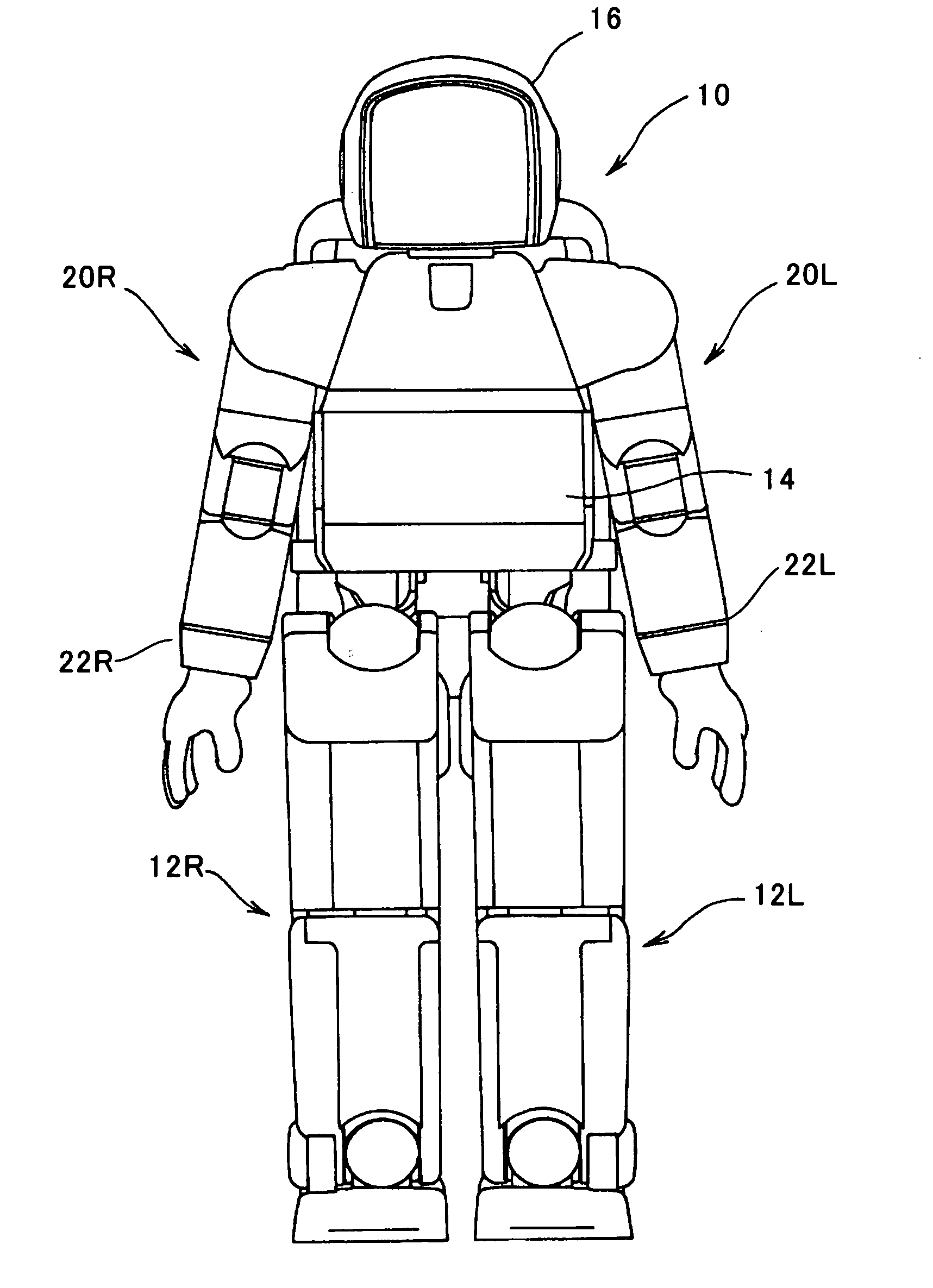
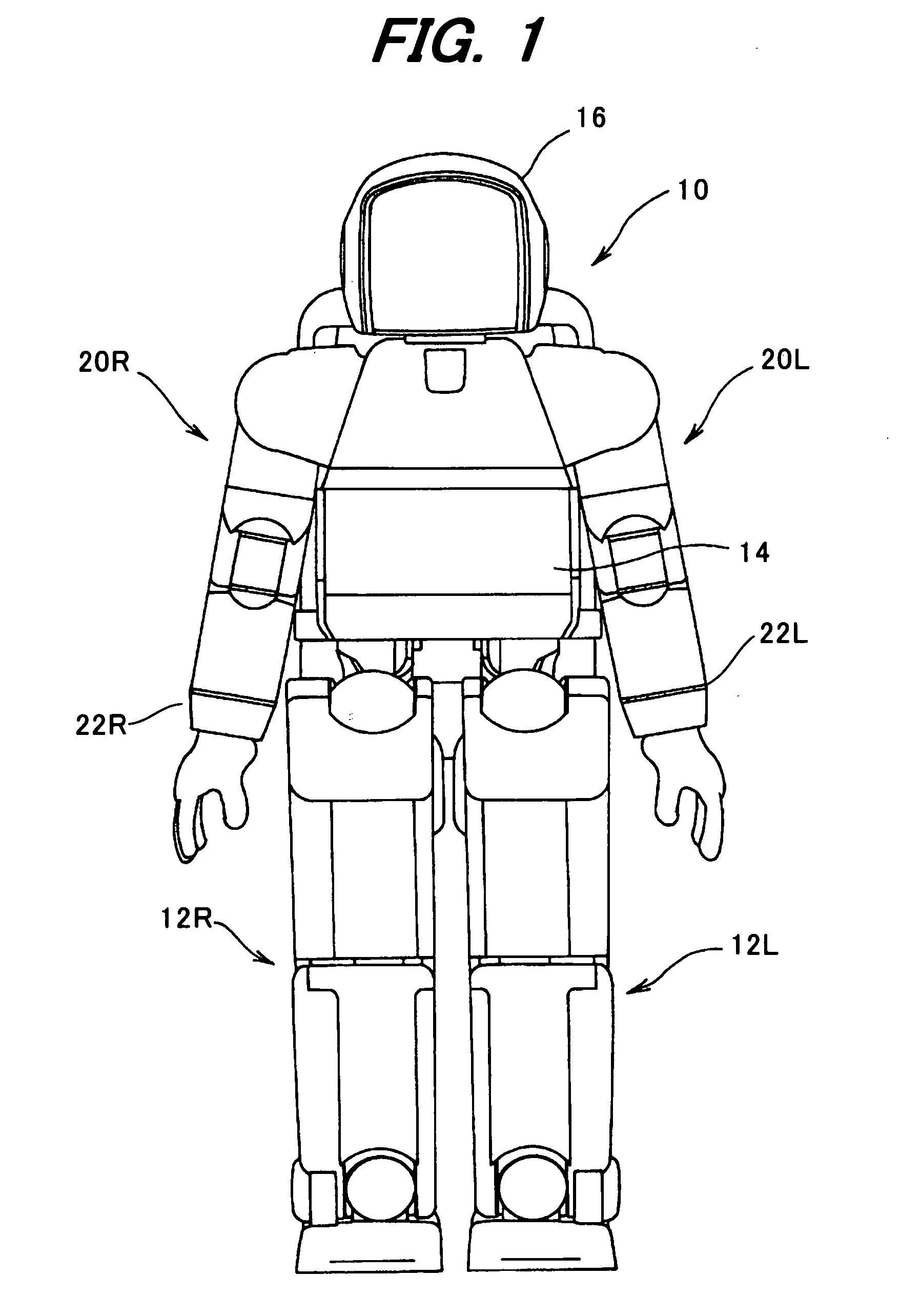
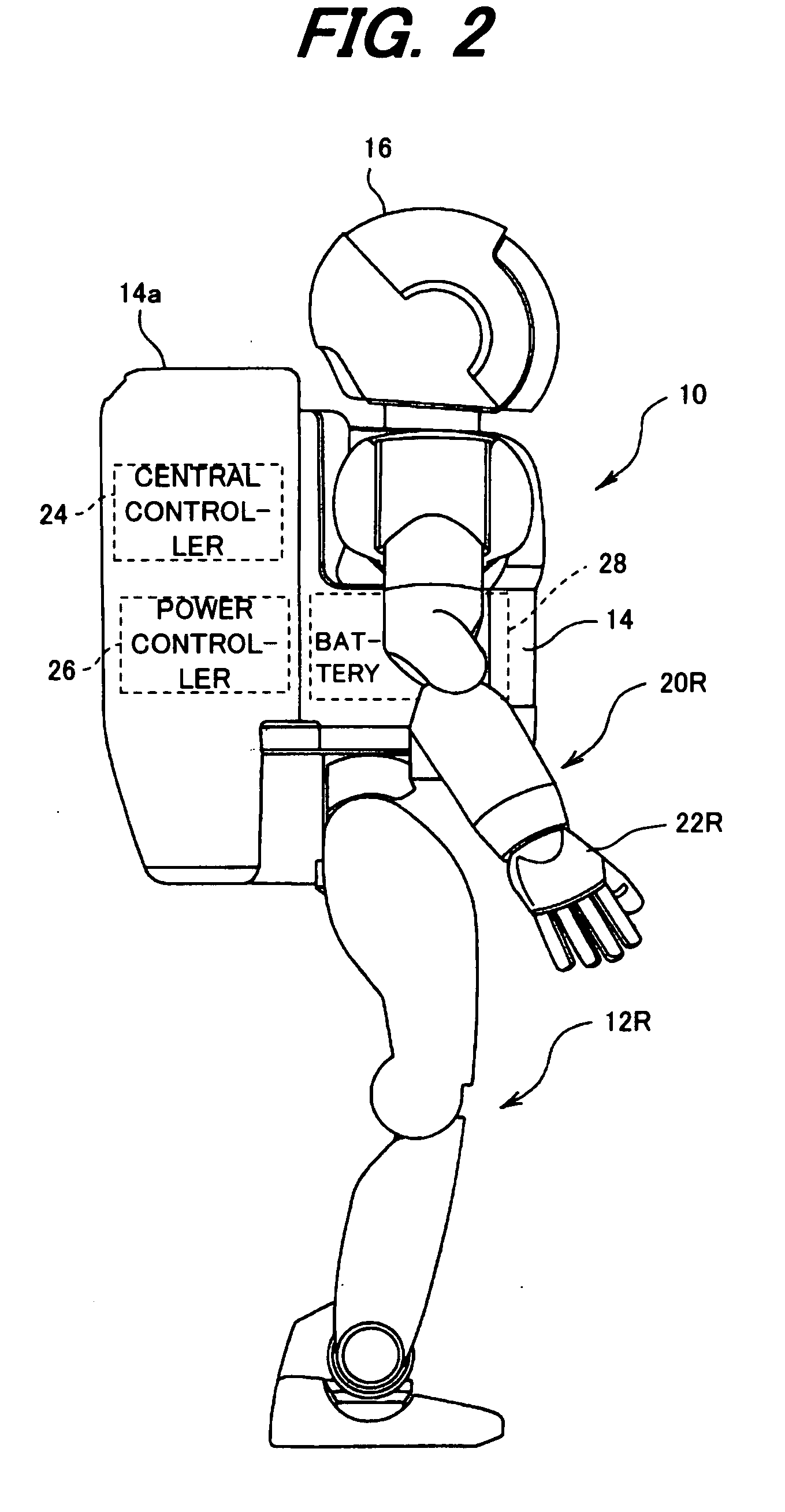
[0028]FIG. 1 is a front view of a robot to which a driving system for a mobile robot according to this invention is applied and FIG. 2 is a side view of the robot shown in FIG. 1. A legged mobile robot with two legs is taken as an example of the mobile robot.
[0029]As shown in FIG. 1, the legged mobile robot (hereinafter called simply “robot”) 10 has a plurality of, i.e., two legs (links), namely with a left leg 12L and a right leg 12R (the symbols L and R are used to indicate the left and right sides; hereinafter the same). The legs 12L, 12R are connected to the bottom of a main body (trunk) 14. A head 16 is connected to the top of the body 14 and a plurality of, i.e., two arms, namely a left arm 20L and a right arm 20R, are connected to the sides of the body 14. Hands or end effectors 22L, 22R are connected to the distal ends of the left and right arms 20L, 20R.
[0030]As shown in FIG. 2, a housing unit 14a is mounted on the back of the body 14. The housing unit 14a accommodates ther...
second embodiment
[0082]It may happen a case where the current feedback gain is decreased before completing the voltage boosting and if so, the motor torque may short. However, since the gain is changed during the upright-standing, this will influence little if the motor torque shortage is slight. This will be the same in the second embodiment in which the gain change is made during the free-leg period. At any rate, the deviation in changing time should preferably be small.
[0083]As described in the foregoing, in the first embodiment, it is configured to have a system for driving the mobile robot 10 having at least a plurality of (two) links (thigh ling 30, shank link 32) each connected by the joint, i.e., one of the hip joint, knee joint and ankle joint, the electric motors (1Y motor 42, 2Y motor 46, 3Y motor 48, 3X motor 50, etc) installed at the joint, the power source (battery) 28 installed at a position other than the links, the power lines 90 connecting the power source to the motors, the motor ...
third embodiment
[0108]FIG. 13 is a flowchart similar to FIG. 7, but showing the operation of a driving system for a mobile robot according to this invention. The shown program is also executed by the central controller 24.
[0109]FIG. 14 is an explanatory view similar to FIGS. 8 and 11, but showing the characteristics of the voltage change with respect to the 2Y motor 46.
[0110]In the third embodiment, as shown in FIG. 14, based on a required joint angular velocity, i.e., a knee joint angular velocity ω [rad / second] estimated from the motion of the robot 10, the voltage levels and setting value of the current feedback gain corresponding thereto are prepared as table values beforehand, thereby enabling a finer control.
[0111]The explanation will be made with focus on points of difference from the first and second embodiments.
[0112]After conducting the processing of S200 to S210 similarly to the first and second embodiments, the program proceeds to S212, in which the joint angular velocity ω is updated. ...
PUM
 Abstract
Description
Claims
Application Information
 - R&D
- Intellectual Property
- Life Sciences
- Materials
- Tech Scout
- Unparalleled Data Quality
- Higher Quality Content
- 60% Fewer Hallucinations
Browse by: Latest US Patents, China's latest patents, Technical Efficacy Thesaurus, Application Domain, Technology Topic, Popular Technical Reports.
© 2025 PatSnap. All rights reserved.Legal|Privacy policy|Modern Slavery Act Transparency Statement|Sitemap|About US| Contact US: help@patsnap.com