
Legged Mobile Robot and Control Program for the Robot

a robot and mobile technology, applied in the field of legged mobile robots, can solve the problems of insufficient deceleration of the foot, inconvenient operation, and actual floor reaction for

Inactive Publication Date: 2008-12-04
HONDA MOTOR CO LTD
View PDF7 Cites 14 Cited by
  • Summary
  • Abstract
  • Description
  • Claims
  • Application Information

AI Technical Summary

Benefits of technology

The present invention relates to a legged mobile robot that can walk and land on different surfaces. The robot has a base body, a plurality of legs, and a compliance mechanism to absorb impact and prevent damage to the robot. The invention provides a control system for the robot that can adjust the force and velocity of the robot's legs to follow a desired floor reaction force and prevent impact and unloading issues. The control system also includes a desired floor reaction force setting, a mechanism deformation amount determining, and a desired ground contacting portion trajectory correcting means to compensate for the influence of mechanism deformation. Overall, the invention allows for smooth unloading and stable control of the robot's operation.

Problems solved by technology

However, if, for example, the desired foot height (desired foot trajectory) as shown in FIG. 19(d) is set, then an inconvenience described below will occur.
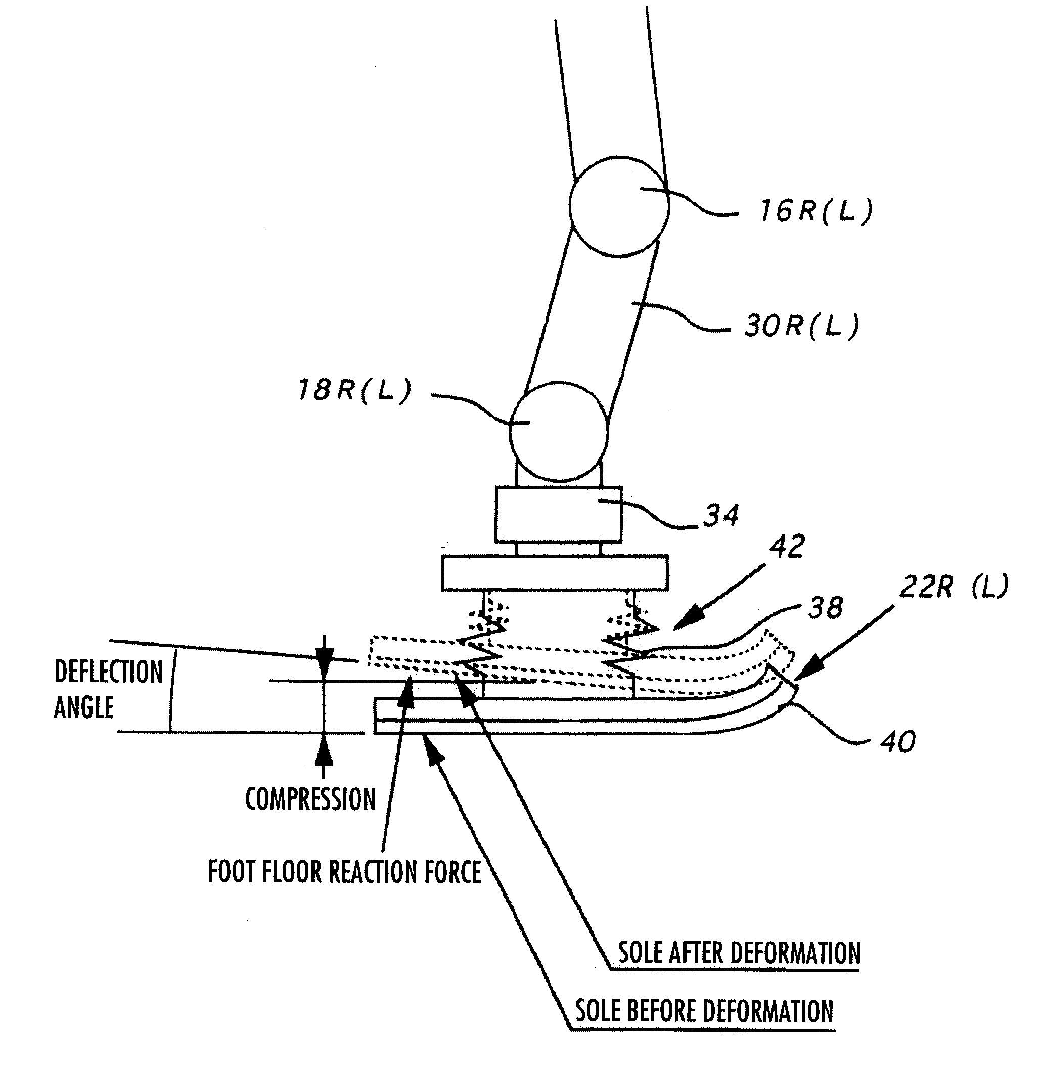
Immediately after a leg moves to a ground-contacting period, an actual floor reaction force starts to develop with a delay with respect to a desired floor reaction force, as shown in FIG. 19(e), leading to a danger in that a foot is not adequately decelerated and the actual floor reaction force and eventually an impact to the robot at landing temporarily become excessive.
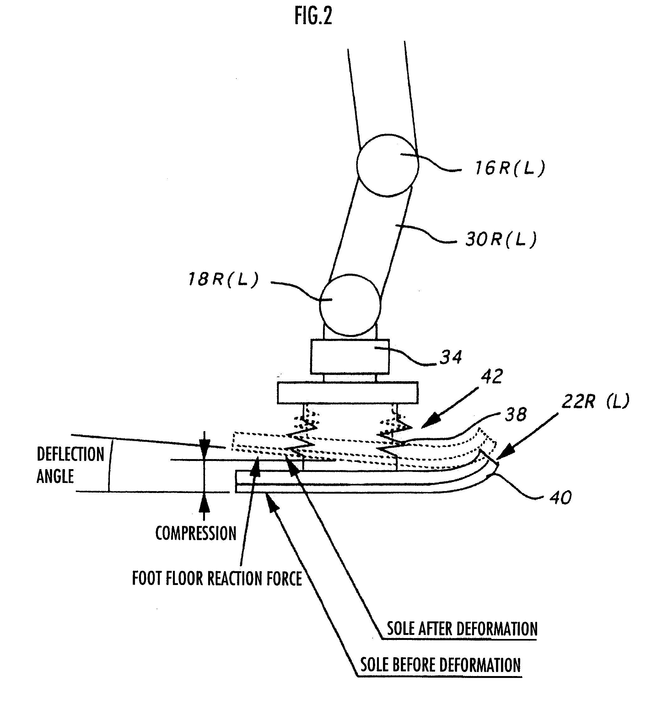
In addition, a time delay may take place in the deformation of the compliance mechanism due to a response delay of an actuator acting as a motor of a leg, a transmission delay in a driving force transmission system, and a response delay due to a deflection in a leg mechanism, leading to a possibility of deterioration in follow-up of an actual floor reaction force acting on a foot (=a floor reaction force measured by a 6-axis force sensor or the like provided on a foot joint) to a desired floor reaction force.
This may cause a toe or the like of the foot to be caught on a floor surface, leading to a possibility of a motion of the robot being disturbed at least temporarily thereafter.

Method used


Image

  • Legged Mobile Robot and Control Program for the Robot
  • Legged Mobile Robot and Control Program for the Robot
  • Legged Mobile Robot and Control Program for the Robot

Examples


first embodiment

[0150]The processing will be explained in conjunction with FIG. 14. First, in S1300, a body vertical position trajectory that satisfies a predetermined geometric restrictive condition related to at least the displacements of the joints of the legs 2 is determined using the body height determining method previously proposed in Japanese Patent Laid-Open Publication No. H10-86080 by the present applicant. Hereinafter, this will be referred to as the reference body vertical position trajectory. To be more specific, first, based on the foot trajectory parameters, the desired ZMP trajectory parameters and the like that have been determined on the basis of required parameters, a body horizontal position trajectory is determined using Japanese Patent Application No. 2000-352011 previously proposed by the present applicant. In this case, the body horizontal position trajectory is determined such that the floor reaction force vertical component agrees with the self-weight of the robot 1 and t...

second embodiment

[0170]the method for controlling the operations of the legs 2 will be explained in conjunction with FIG. 17 and FIG. 18.

[0171]First, it is determined whether the foot (the ground contacting portion) 22 is in contact with a floor, that is, whether the foot 22 is in the landing-on-floor period or the leaving-from-floor period (S2200).

[0172]If it is determined that the foot 22 is in the landing-on-floor period (S2200 . . . YES), then a mechanism deformation amount is calculated on the basis of a desired floor reaction force instantaneous value (S2202), then a corrected foot position / posture trajectory with deformation compensation is determined on the basis of a desired foot position / posture trajectory and the mechanism deformation amount (S2210).

[0173]Specifically, based on the component of the desired floor reaction force (instantaneous value) in the vertical direction or the component thereof in the direction perpendicular to a floor surface in the landing-on-floor period shown in F...


PUM


Abstract

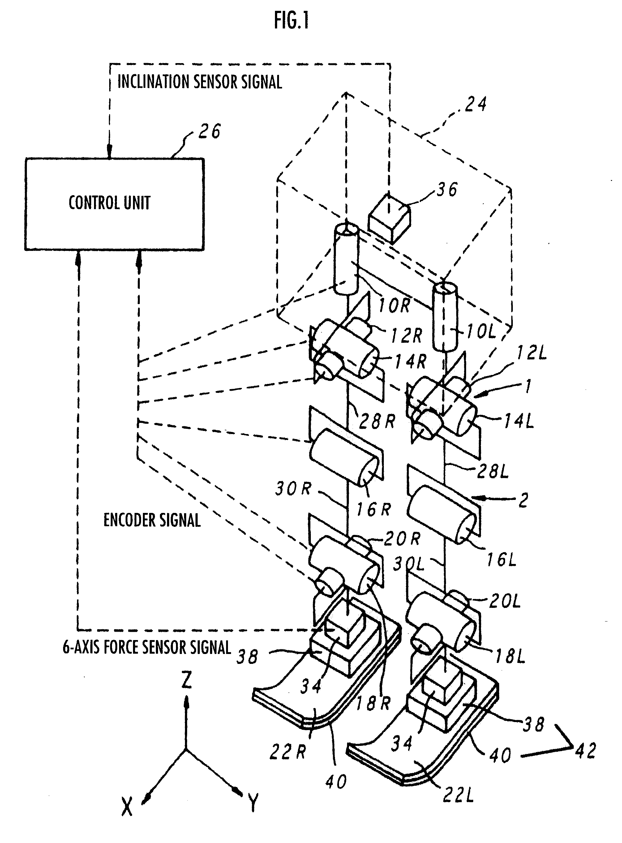
A legged mobile robot which permits improved follow-up of an actual floor reaction force to a desired floor reaction force and which can be stably controlled is provided.According to a robot 1 in accordance with the present invention, a deformation amount (mechanism deformation amount) of a compliance mechanism 42 that occurs due to a desired floor reaction force of a foot (ground contacting portion) 22 is determined, and the operation of a leg 2 is controlled such that the foot 22 lands onto a floor at a predetermined velocity in a vertical direction or in a direction perpendicular to the floor surface on the basis of a component of the mechanism deformation amount in the vertical direction or a component thereof in the direction perpendicular to the floor surface.

Description

TECHNICAL FIELD[0001]The present invention relates to a legged mobile robot and a control program for the same.BACKGROUND ART[0002]Hitherto, there has been proposed a technical approach for controlling an operation of a leg when a robot travels such that a vertical component of the velocity of a foot approximates zero before landing so as to ease an impact to the leg and the like when the foot lands on a floor. With this arrangement, when, for example, a bipedal mobile robot runs by repeating a floating period during which both legs are in the air and a one-leg supporting period during which the robot is supported by one of the legs, a desired foot height of the right foot is set such that it reaches zero immediately before the floating period is switched to the one-leg supporting period, as shown in FIG. 19(a).[0003]There has been proposed another technical approach in which a compliance mechanism for reducing an impact to a leg and the like when a foot lands on a floor is provided...

Claims


Application Information

Patent Timeline
Patent Type & Authority Applications(United States)
IPC IPC(8): B25J5/00B25J13/00
CPCB62D57/032B25J13/00B25J5/00
Inventor TAKENAKA, TORUMATSUMOTO, TAKASHIYOSHIIKE, TAKAHIDEAKIMOTO, KAZUSHISHIROKURA, SHINYAASATANI, MINAMI
Owner HONDA MOTOR CO LTD
Learn More