
Equal sized spherical beads

a technology of equal sized spherical beads and beads, which is applied in the direction of grinding devices, manufacturing tools, other chemical processes, etc., can solve the problems of waste, undersized beads that are not used in the abrading process, and expensive materials commonly used in including diamond particles

Inactive Publication Date: 2008-12-04
DUESCHER WAYNE O
View PDF100 Cites 131 Cited by
  • Summary
  • Abstract
  • Description
  • Claims
  • Application Information

AI Technical Summary

Benefits of technology

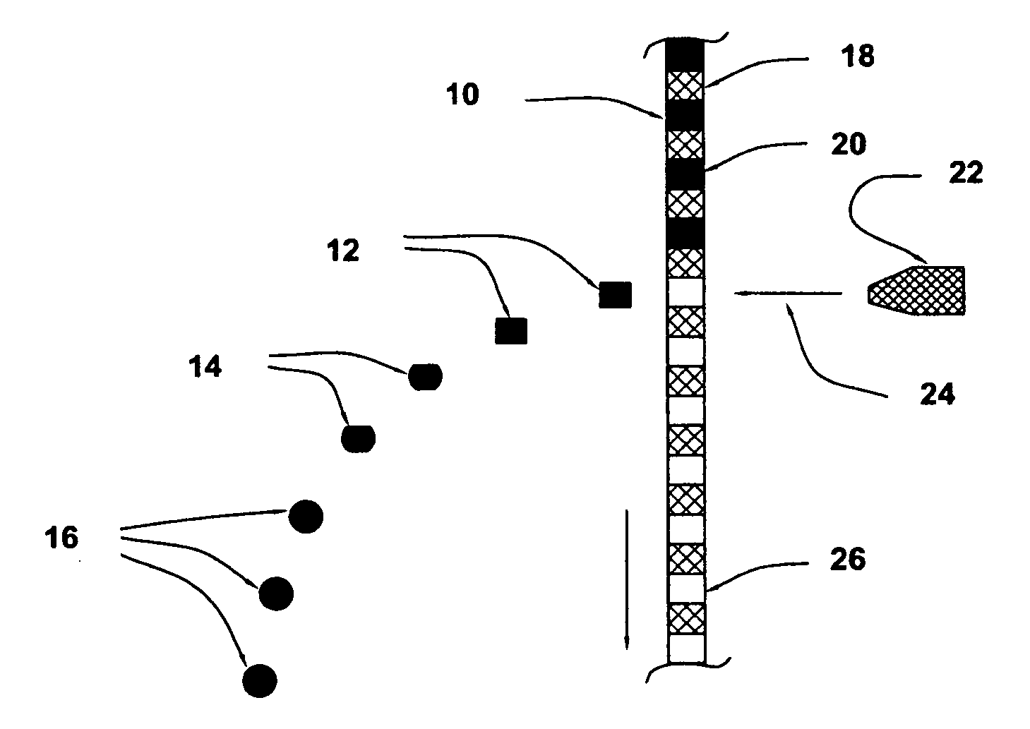
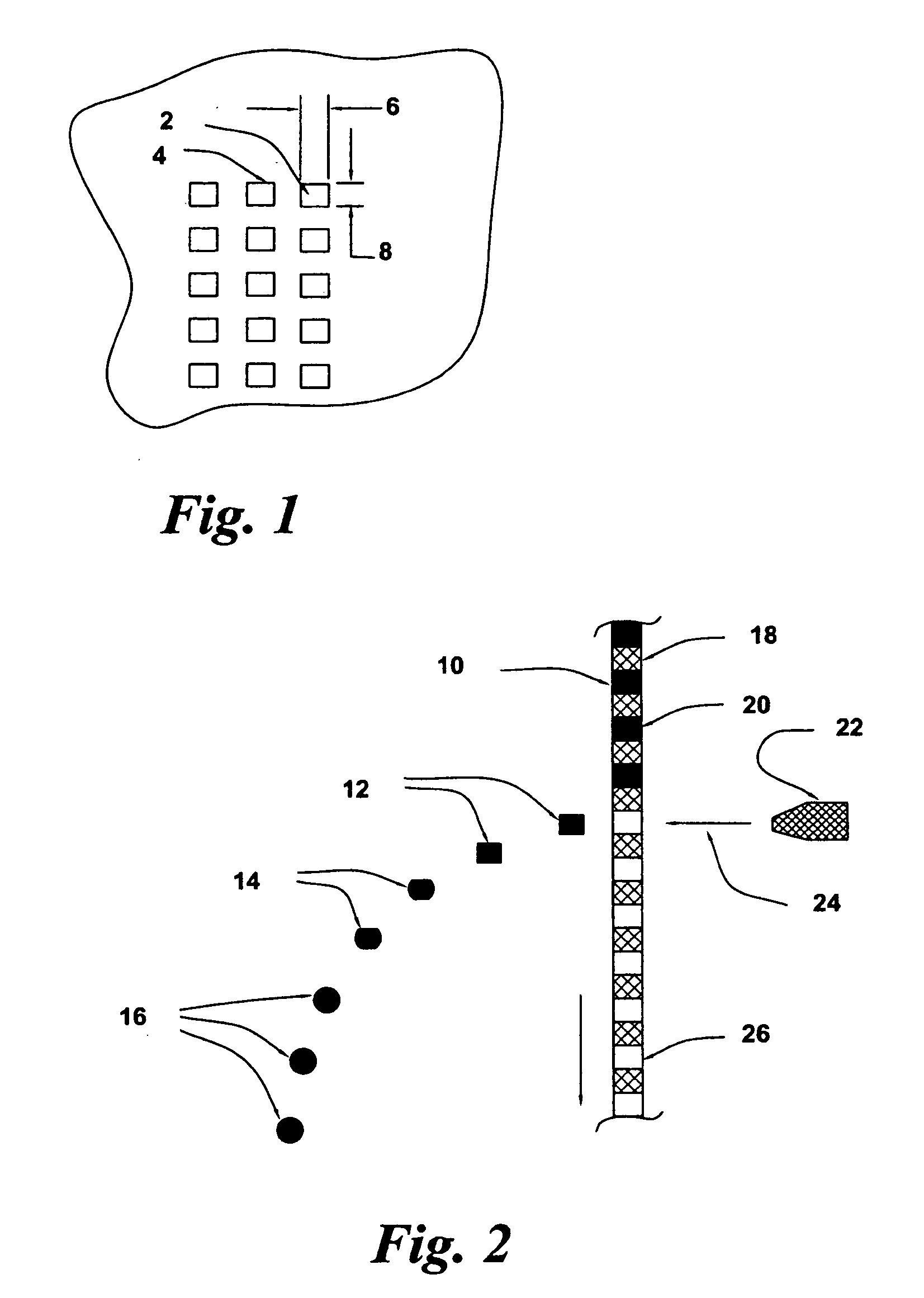
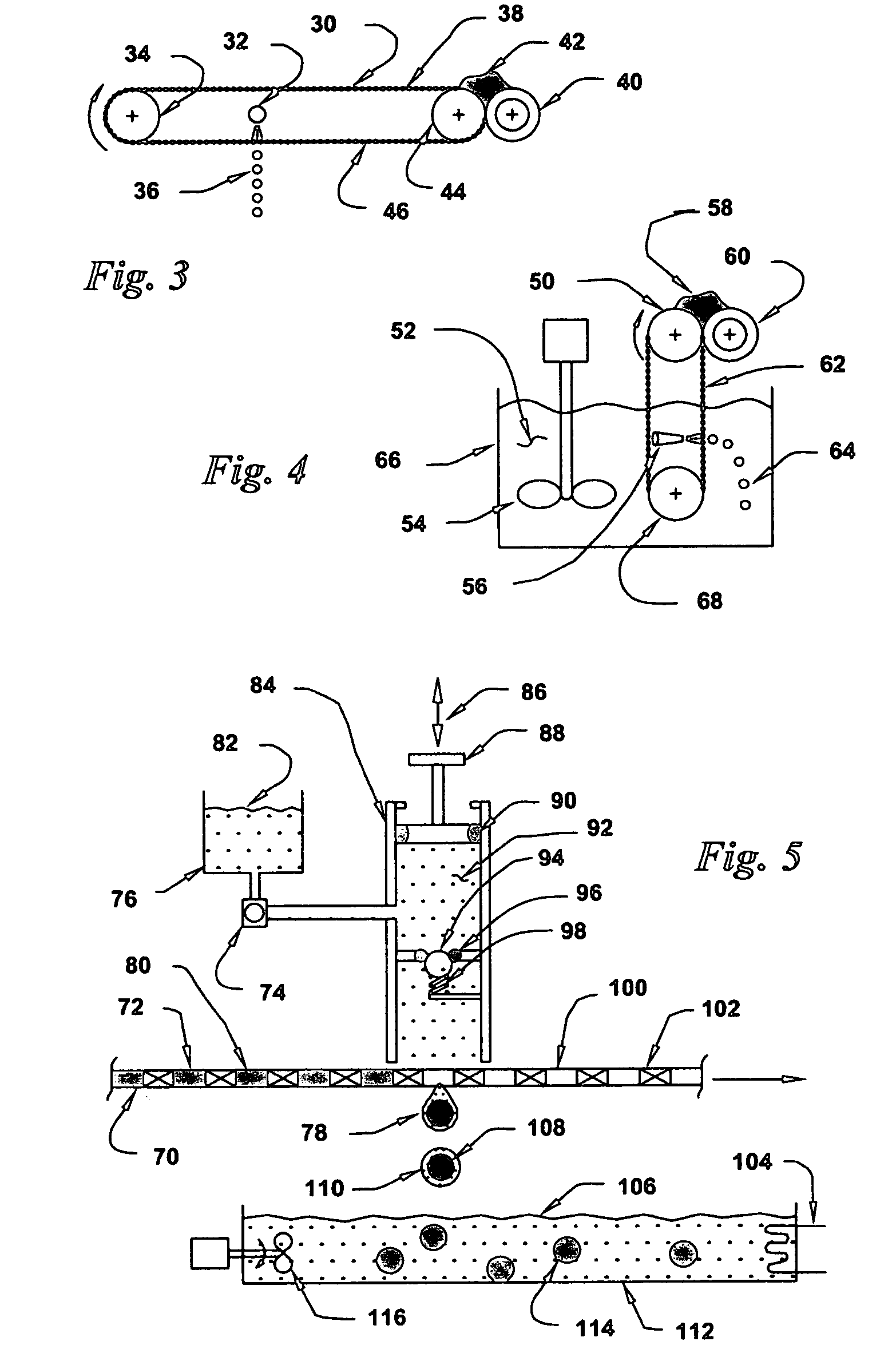
[0055]A method to produce equal sized spherical beads from a wide range of materials is described. These spheres can contain abrasive particles that can be coated on the surface of a backing to produce an abrasive article. The spheres can contain other particles or simply consist of ceramic or other materials. After solidifying the spherical beads in an solidifying environment, the spherical particles can be further solidified in heated air or by using other solidifying techniques well know in the art.

Problems solved by technology

If undersized beads are mixed with full sized beads and coated on the surface of abrasive articles, the undersized beads are often not used in the abrading process as they are too small to come into contact with a workpiece surface.
This means also, that the expensive materials commonly used in including diamond particles, are wasted as they are not used.
His system is not capable of making spherical abrasive particles.
Also, spherical abrasive particles made of his materials by his system would be useless for abrading purposes because the resultant spherical particles do not provide sharp cutting edges.
They can not formed a gelled dispersion solution into a spherical shape.
If these particles were to fuse to each other while residing in the collection pan, those sharp edges of one particle that were joined with an adjacent particle would be destroyed, which would be an very undesirable event for Berg.
However, if Berg has a defective mold filling process where some of his gelled dispersion overfills the individual mold cavities and the dispersion is inadvertently smeared in a thin layer along the flat surface of the mold sheet, the smeared dispersion portion tends to overhang the edges of the mold cavity.
However, because the overhang dispersion material is thin and the solidified dispersion is relatively weak at this stage of gelled solidification, the overhanging edges of the lodged particles can be easily broken off with a small externally applied pressure.
This edge-breakage produces defective abrasive particles that have non-sharp cutting edges on those particle edges (only) that were broken off in the pressure ejection process.
The debris reduces the quality of his abrasive particle product unless it is separated out, which requires an extra manufacturing step.
The production of non-spherical dispersion entities is considered to be a failure of this abrasive bead manufacturing process.
If his entities did stick together during this common-particle collection event, the sharp edges that he so painstakingly formed on his individual abrasive precusor particles would be lost when adjacent particles merged together into a common mass.
Further, even though his ejected particles still contain significant amounts of water, including bound-water, these same ejected particles are not rounded by surface tension forces because they would lose their sharp edges if they did become so-rounded in this post-ejection event.
It would not be possible to substitute a woven wire screen for Berg's cavity molds to manufacture his dispersion entities.
However, the entity shrinkage will not be sufficient that the non-joined solidified entities will pass through the screen cell openings.
Berg can not use a woven screen to process his dispersion entities because the trapped solidified entities can not be ejected from the individual woven wire screen cells.
Also, it would not be practical or desirable to incorporate pre-formed sharp diamond particles into Berg's hardened aluminum oxide abrasive particles because of the degradation of the diamond material at the high firing temperatures required to harden his aluminum oxide materials sufficiently that they can be used as an abrasive material.

Method used


Image

  • Equal sized spherical beads
  • Equal sized spherical beads
  • Equal sized spherical beads

Examples


Embodiment Construction

[0070]Abrasive particles or abrasive agglomerates can range in size from less than 0.1 micron to greater than 400 microns. In the abrasive agglomerates, hard abrasive particle grains are distributed uniformly throughout a matrix of erodible material including softer microporous metal or non-metal oxides (e.g., silica, alumina, titania, zirconia-silica, magnesia, alumina-silica, alumina and boria or boria) or mixtures thereof including silica-alumina-boria or others.

[0071]Near-spherical composite abrasive shapes can be produced by creating agglomerates of an water based abrasive slurry that are dried when free-span travelling in heated air or in a dehydrating liquid during which time surface tension forces tend to produce near-spherical shapes prior to solidification of the agglomerates. A desirable size of agglomerates having 10 micron or less abrasive particles is 30 to 45 microns or less and a desirable size of agglomerates having 25 micron or less abrasive particles is 75 microns...


PUM

PropertyMeasurementUnit
diameteraaaaaaaaaa
diameteraaaaaaaaaa
travel distanceaaaaaaaaaa

Abstract

A method of producing equal-sized spherical shaped beads of a wide range of materials is described. These beads are produced by forming the parent bead material into a liquid solution and by filling equal volume cells in a sheet with the liquid solution. The sheet cells establish the volumes of each of the cell mixture volumes which are then ejected from the cells by an impinging fluid. Surface tension forces acting on the ejected equal sized solution entities form them into spherical beads. The ejected beads are then subjected to a solidification environment which solidifies the spherical beads. The beads can be solid or porous or hollow and can also have bead coatings of multiple material layers.

Description

CROSS REFERENCE TO RELATED APPLICATION[0001]This invention is a continuation-in-part of U.S. patent application Ser. No. 12 / 217,565 filed Jul. 7, 2008, which is a continuation-in-part of U.S. patent application Ser. No. 11 / 029,761 filed Jan. 5, 2005, which is a continuation-in-part of U.S. patent application Ser. No. 10 / 816,275 filed Aug. 16, 2004, which is a continuation-in-part of U.S. patent application Ser. No. 10 / 824,107 filed Apr. 14, 2004, which is a continuation-in-part of U.S. patent application Ser. No. 10 / 418,257, filed Apr. 16, 2003, now Abandoned, which is a continuation-in-part of U.S. patent application Ser. No. 10 / 015,478 filed Dec. 13, 2001, now U.S. Pat. No. 6,752,700, which is a continuation-in-part of U.S. patent application Ser. No. 09 / 715,448 filed Nov. 17, 2000, now U.S. Pat. No. 6,769,969, and which applications are incorporated herein by reference.BACKGROUND OF THE ARTField of the Invention[0002]The present invention relates to forming equal sized spherical ...

Claims


Application Information

Patent Timeline
Patent Type & Authority Applications(United States)
IPC IPC(8): B24B1/00
CPCB24D18/00Y10T29/49982Y10T29/4998
Inventor DUESCHER, WAYNE O.
Owner DUESCHER WAYNE O
Learn More