
Method of manufacturing semiconductor light-emitting element

a light-emitting element and manufacturing method technology, applied in semiconductor devices, lasers, semiconductor lasers, etc., can solve the problems of affecting the operation of the device, so as to reduce the operating voltage, reduce the concentration of the carrier, and reduce the electrical resistivity.

Inactive Publication Date: 2008-12-04
SUMITOMO ELECTRIC IND LTD
View PDF2 Cites 0 Cited by
  • Summary
  • Abstract
  • Description
  • Claims
  • Application Information

AI Technical Summary

Benefits of technology

[0008]That is, an object of this invention is to provide a method of manufacture of a semiconductor light-emitting device with further improved element characteristics.
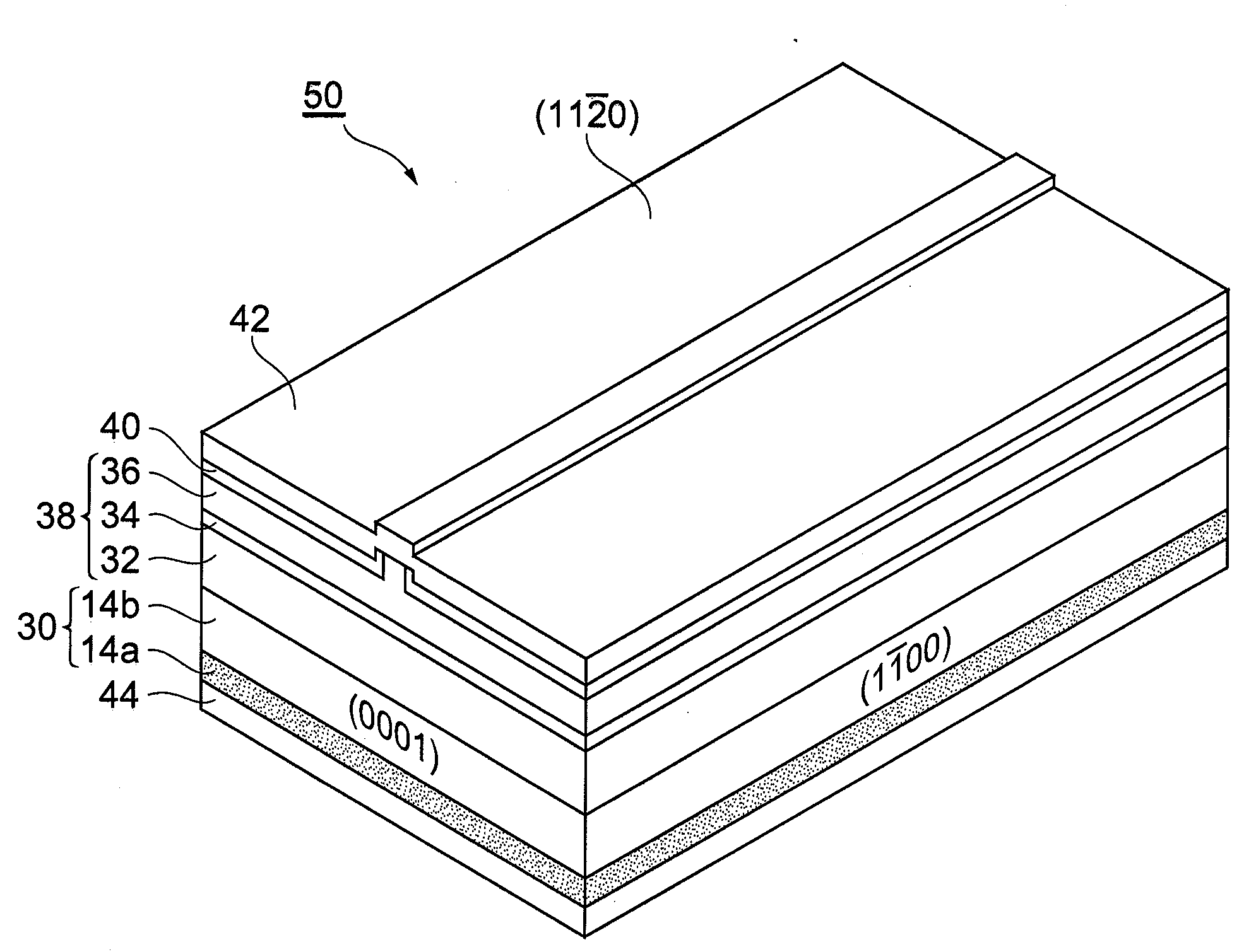
[0010]In this semiconductor light-emitting element manufacturing method, the GaN single-crystal substrate is formed by slicing a GaN bulk crystal, grown on the c-plane, parallel to the a-plane perpendicularly intersecting the c-plane. Such substrates are not readily affected by crystal defects extending parallel to the c axis direction, and degradation of element characteristics due to crystal defects can be suppressed. Further, because the a-plane is a nonpolar plane, light emission efficiency can be further improved compared with the c-plane, which is a polar plane. Further, at the surface of a GaN bulk crystal in which defect aggregation portions are formed, there is a tendency for height differences to occur between defect aggregation portions and remainder portions, and degradation of element characteristics can occur due to these height differences. However, in a substrate obtained by slicing parallel to the a-plane, satisfactory surface flatness is obtained, so that such element characteristic degradation can be effectively avoided. Hence by means of a semiconductor light-emitting element manufacturing method of this invention, further improvement of the element characteristics of manufactured semiconductor light-emitting elements can be realized.
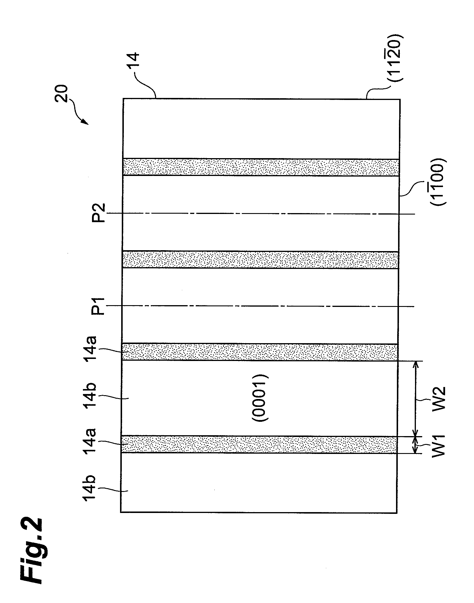
[0012]Further, in the substrate formation process, slicing may be performed at positions with the defect aggregation portion interposed therebetween, and GaN single-crystal substrates formed with defect aggregation portions exposed at one face thereof. Because there are numerous crystal defects in defect aggregation portions, carrier concentrations are high, and electrical resistivity is lowered significantly. Hence by using a substrate in which such a defect aggregation portion is exposed as a substrate for element formation, a semiconductor light-emitting element with a lowered operating voltage can be fabricated.

Problems solved by technology

Further, at the surface of a GaN bulk crystal in which defect aggregation portions are formed, there is a tendency for height differences to occur between defect aggregation portions and remainder portions, and degradation of element characteristics can occur due to these height differences.

Method used


Image

  • Method of manufacturing semiconductor light-emitting element
  • Method of manufacturing semiconductor light-emitting element
  • Method of manufacturing semiconductor light-emitting element

Examples


Embodiment Construction

[0019]Below, aspects thought to be optimal when implementing the invention are explained in detail, referring to the attached drawings. Elements which are the same or equivalent are assigned the same symbols, and redundant explanations are omitted.

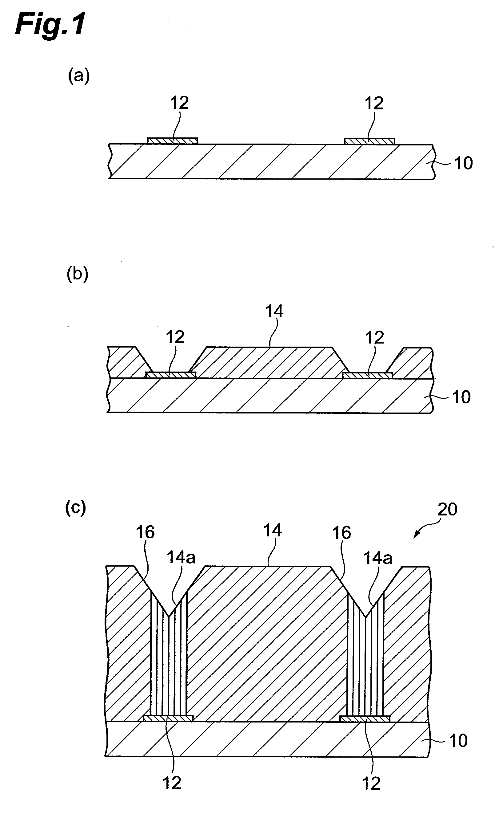
[0020]First, a procedure for manufacturing GaN single-crystal substrates used in manufacturing semiconductor light-emitting elements of this aspect of the invention is explained, referring to FIG. 1.

[0021]In fabricating the GaN single-crystal substrate, a prescribed single-crystal substrate 10 is used. As this single-crystal substrate 10, in addition to GaN substrate, a sapphire substrate, GaAs substrate, Si substrate, or similar, onto which a GaN epitaxial layer has been grown, can be used. The c-plane is exposed as the growth plane (surface) of this single-crystal substrate 10.

[0022]As shown in (a) of FIG. 1, a stripe-shape mask layer 12 is patterned and formed on the surface of the single-crystal substrate 10. The constituent material o...


PUM


Abstract

In a semiconductor laser manufacturing method, a GaN single-crystal substrate is formed by slicing a GaN bulk crystal, grown on a c-plane, parallel to an a-plane which is perpendicular to the c-plane. In this substrate, crystal defects extending parallel to the c-axis direction do not readily exert an influence, and degradation of element characteristics due to crystal defects can be suppressed. Further, because the a-plane is a nonpolar plane, improved light emission efficiency and longer wavelengths can be achieved compared with the c-plane, which is a polar plane. Hence a semiconductor laser manufacturing method of this invention enables further improvement of the element characteristics of the semiconductor laser to be fabricated.

Description

BACKGROUND OF THE INVENTION[0001]1. Field of the Invention[0002]The present invention relates to a method of manufacturing a semiconductor light-emitting element.[0003]2. Related Background Art[0004]In the prior art, GaN single-crystal substrates have been used in the manufacture of semiconductor lasers, light-emitting diodes, and other semiconductor light-emitting elements. For example, such methods are disclosed in Applied Physics Letters, Vol. 85, No. 22 (2004), p. 5143-5145, and in Japanese Journal of Applied Physics, Vol. 45, No. 45 (2006), p. L1197-L1199, which are non-patent references.[0005]It is know that when the GaN single-crystal substrate used has numerous crystal defects, there is degradation of the light emission intensity, element lifetime, and other characteristics of the semiconductor light-emitting element. Hence the inventors presented, in Japanese Unexamined Patent Publication No. 2003-183100, a GaN single-crystal substrate grown on a c-plane and manufacturing m...

Claims


Application Information

Patent Timeline
Patent Type & Authority Applications(United States)
IPC IPC(8): H01L33/00H01L33/32
CPCH01S5/0202H01S5/2201H01S5/3202H01S5/32341H01S2301/173H01S2304/12H01S5/320225
Inventor AKITA, KATSUSHIKASAI, HITOSHIMIURA, YOSHIKIMOTOKI, KENSAKU
Owner SUMITOMO ELECTRIC IND LTD
Learn More