
Developing unit and image forming device

a technology of developing unit and image forming device, which is applied in the direction of instruments, electrographic process devices, optics, etc., can solve the problems of high electric resistance, leakage of electric current between the developing roller and the photoreceptor, and difficulty in forming a toner image accurately representing the electrostatic

Active Publication Date: 2009-07-16
KYOCERA DOCUMENT SOLUTIONS INC
View PDF4 Cites 2 Cited by
  • Summary
  • Abstract
  • Description
  • Claims
  • Application Information

AI Technical Summary

Benefits of technology

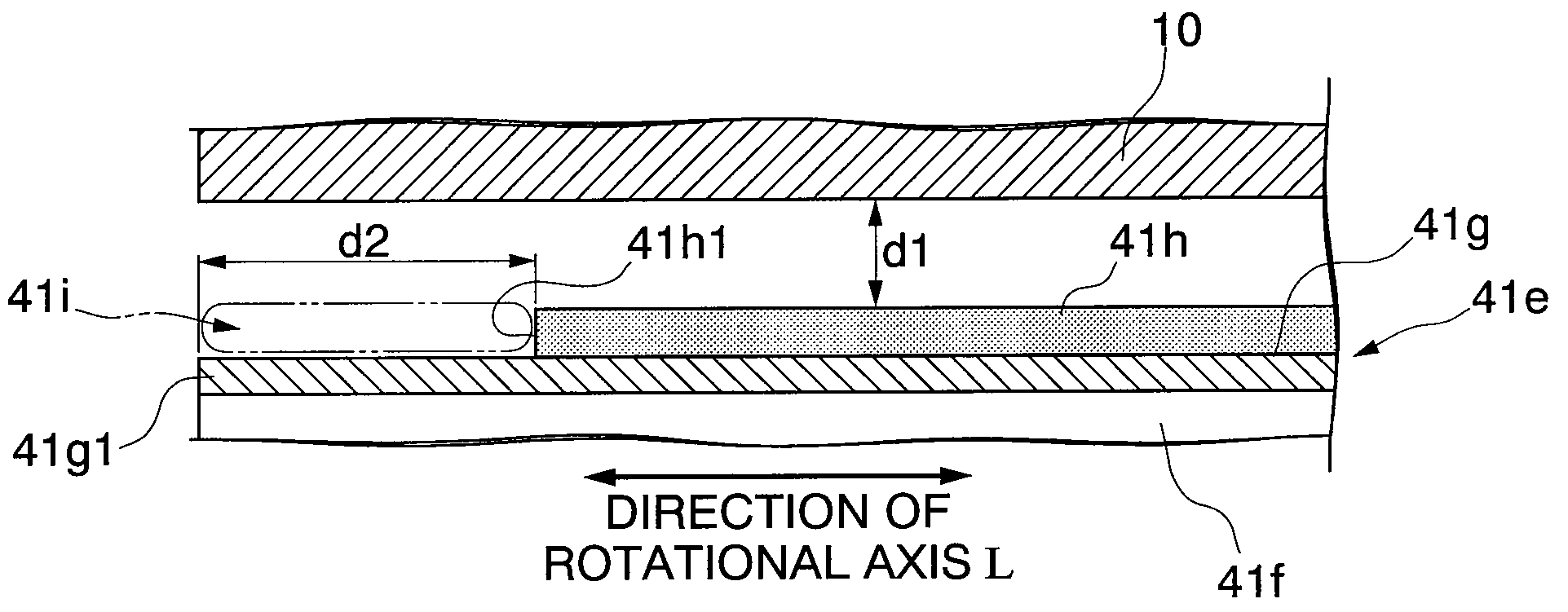
[0013](1) A first aspect of the present invention provides the following: a developing unit including a developing roller which rotates about a rotational axis to supply toner to a photoreceptor, the developing roller including: a cylindrical core portion which includes an electric conductor; a first resistive layer which covers a cylindrical surface of the core portion; a second resistive layer which covers the first resistive layer, and has electric-resistivity lower than that of the first resistive layer; and a current leakage control member which prevents leakage of electric current from the core portion toward the second resistive layer through an end of the developing roller along a direction of the rotational axis.
[0014]According to the developing unit, the current leakage control member prevents leakage of electric current from the core portion into the second resistive layer through the end of the developing roller along the direction of the rotational axis. The second resistive layer, having resistivity lower than that of the first resistive layer, prevents charge injection into the toner and thus excessive charging of the toner.
[0015]Accordingly, defective toner transfer to the photoreceptor due to excessive charging of the toner can be prevented and leakage of electric current from between the developing roller and the photoreceptor can also be prevented.

Problems solved by technology

However, if the developing roller and the photoreceptor are disposed close to each other with the voltage applied to produce a predetermined potential difference therebetween, leakage of electric current from between the developing roller and the photoreceptor may occur, so that it is difficult to form a toner image which accurately represents the electrostatic latent image on the photoreceptor, and a toner layer on the surface of the developing roller.
Alumite, however, has a high electric-resistivity, which may cause excessive charging of the toner due to friction between the toner and the developing roller.
As a result, the toner turnover efficiency may become lower.
If a low-resistance layer is formed on top of the alumite layer, however, electric current may leak into the low-resistance layer from a portion of the electric conductor which forms a core material at an end of the developing roller.

Method used


Image

  • Developing unit and image forming device
  • Developing unit and image forming device
  • Developing unit and image forming device

Examples


Embodiment Construction

[0029]In reference to the drawings, embodiments of the developing unit and the image forming device according to the present invention will be described. In the drawings, the members are not to scale, but are depicted in a visually understandable manner. In the following description, a copier will be illustrated as an example of the image forming device according to the present invention.

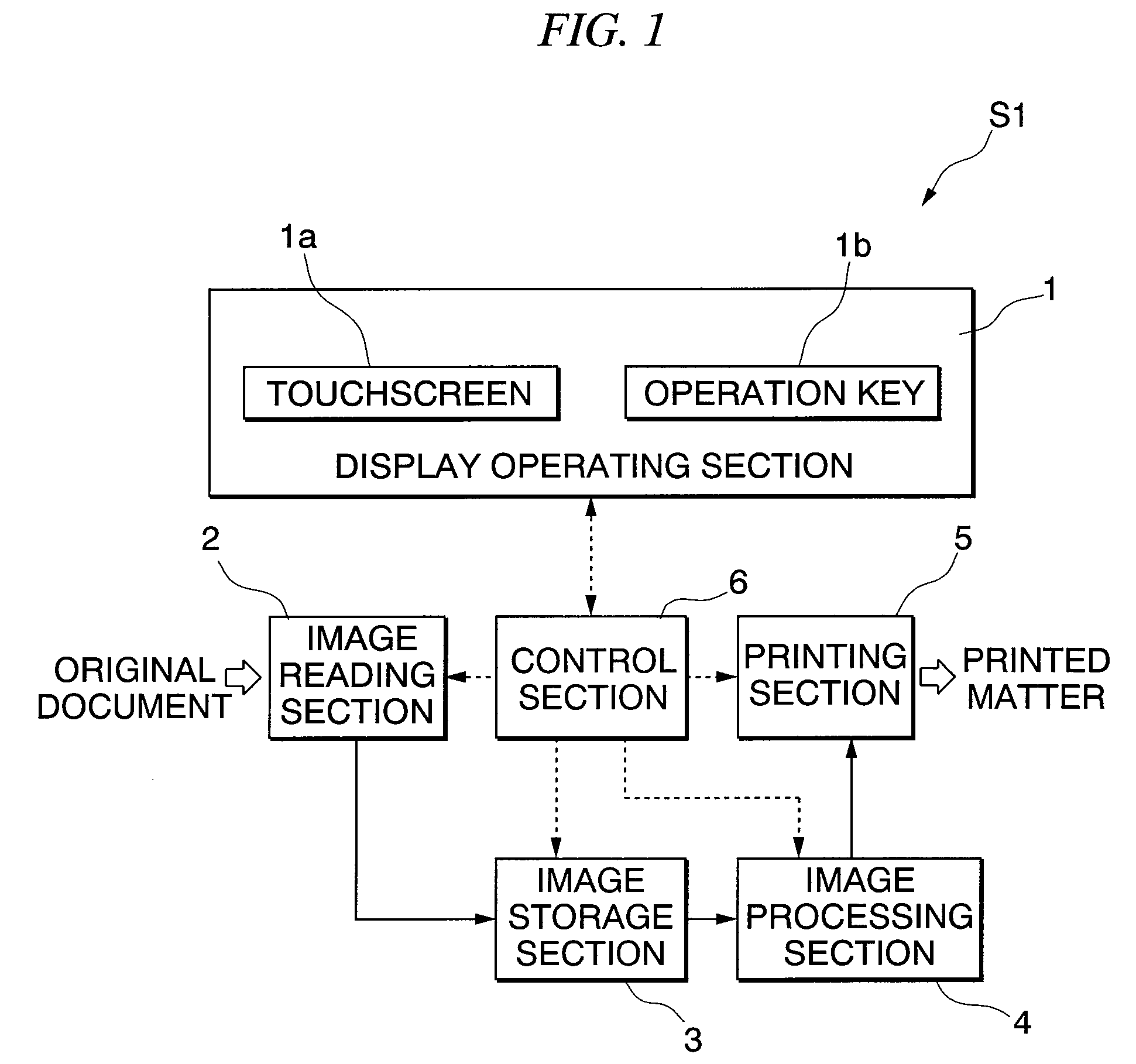
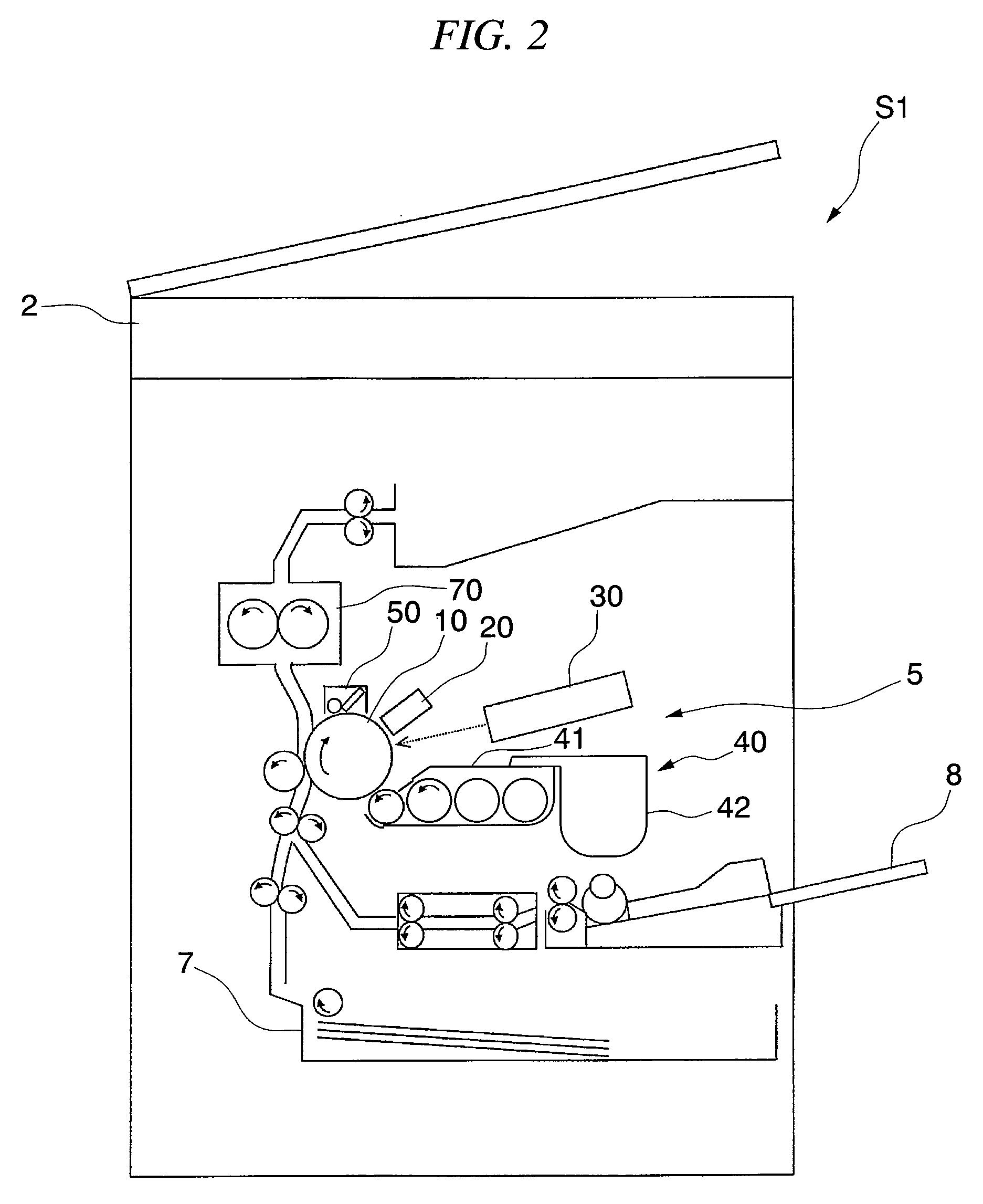
[0030]FIG. 1 is a block diagram showing a functional configuration of a copier S1 (i.e., an image forming device) according to the present embodiment. FIG. 2 is a schematic diagram of a configuration of the copier S1.

[0031]As shown in FIG. 1, the copier S1 includes a display operating section 1, an image reading section 2, an image storage section 3, an image processing section 4, a printing section 5 and a control section 6.

[0032]In the present embodiment, the copier S1 use a two-component developing agent, in which magnetic powder is used as a carrier together with toner. The copier S1 performs so...


PUM


Abstract

A developing unit includes a developing roller which rotates about a rotational axis to supply toner to a photoreceptor, the developing roller including: a cylindrical core portion which includes an electric conductor; a first resistive layer which covers a cylindrical surface of the core portion; a second resistive layer which covers the first resistive layer, and has electric-resistivity lower than that of the first resistive layer; and a current leakage control member which prevents leakage of electric current from the core portion toward the second resistive layer through an end of the developing roller along a direction of the rotational axis.

Description

BACKGROUND OF THE INVENTION[0001]1. Field of the Invention[0002]The present invention relates to a developing unit and an image forming device.[0003]Priority is claimed on Japanese Patent Application No. 2008-005936, filed Jan. 15, 2008, and the content of which is incorporated herein by reference.[0004]2. Description of the Related Art[0005]A known image forming device used for a copier or a printer includes a developing unit for developing an electrostatic latent image formed on a photoreceptor with toner supplied to the photoreceptor. In such a device, the toner is transferred to the photoreceptor from a toner layer formed on a surface of a developing roller. The developing roller is a cylindrical electric conductor provided in the developing unit.[0006]In such an image forming device, voltage is applied to the device to produce a predetermined potential difference between the developer roller and the photoreceptor in order to transfer the toner from the developing roller to the ...

Claims


Application Information

Patent Timeline
Patent Type & Authority Applications(United States)
IPC IPC(8): G03G15/08
CPCG03G15/0818
Inventor HAMAKAWA, HIROYUKIWATANABE, AKIHIROFUJISHIMA, MASASHIYAMAZAKI, HIROSHIKOTERA, ASAMIUEMURA, SAYO
Owner KYOCERA DOCUMENT SOLUTIONS INC
Learn More