Cylinder apparatus and disk brake

a technology of cylinder apparatus and disk brake, which is applied in the direction of hydraulic cylinder brake, fluid actuated drum brake, braking system, etc., can solve the problems of increasing the overall number of parts used, corresponding increase in parts costs, and significant increase in processing costs, so as to avoid unnecessary movement of the tool, reduce the effect of strength and no reduction of strength

Active Publication Date: 2008-11-27
HITACHI ASTEMO LTD
View PDF10 Cites 6 Cited by
  • Summary
  • Abstract
  • Description
  • Claims
  • Application Information

AI Technical Summary

Benefits of technology

[0008]In the cylinder apparatus according to the present invention, the covering member in the bottom portion of the cylinder apparatus is friction stir welded to the cylinder body. This makes it possible to hermetically integrate the covering member with the cylinder body and, therefore, eliminates the need for: forming threads on the covering member and the cylinder body; providing a seal groove; providing a hexagonal socket or the like for engagement with a welding tool; and so on. As a result, processing costs can be reduced, and the apparatus can be reduced in size. Further, since a seal ring is not required, the parts' costs can be reduced. Moreover, fluid leakage associated with seal ring degradation due to ageing is avoided. Further, compared to a structure in which separate component parts are employed, use of an integral structure of the present invention formed by the covering member and the cylinder body enables a hermetic sealing state to be reliably maintained, which further ensures that there is no fluid leakage. In addition, integration of the covering member and the cylinder body enables a number of parts used to be reduced, resulting in correspondingly lower management costs. Further, since use of friction stir welding enables parts to be connected at a relatively low temperature, highly precise dimensions for a processed cylinder apparatus can be obtained.
[0025]The bores may be disposed in an opposing relation to each other; the opposing bores communicate with each other through a communication passage; and an end position of the friction stir welding process, in which the covering member is friction stir welded to the cylinder body, is disposed at such a position that an opening of the communication passage is closed. In this way, the communication passage can be closed by way of friction stir welding. This eliminates the need for closing the communication passage by a separate component. Therefore, the costs of both parts and assembly can be reduced. Further, precision required when such a closure component is connected to the opening of the communication passage is not necessary, which further reduces processing costs.

Problems solved by technology

This significantly increases processing costs.
Further, use of a seal ring causes an increase in an overall number of parts used, and, therefore, a corresponding increase in parts' costs.
Further, use of a seal ring gives rise to a danger of fluid loss (fluid leakage) due to elastic deformation or the like of the seal ring.
These problems relate not only to disk brakes, but also to a variety of other cylinder apparatuses in which a structure is employed wherein an opening of a cylinder body is closed by a covering member.

Method used


Image

  • Cylinder apparatus and disk brake
  • Cylinder apparatus and disk brake
  • Cylinder apparatus and disk brake

Examples


first embodiment

[0051]Below, the present invention will be described in detail with reference to FIGS. 1 to 7.

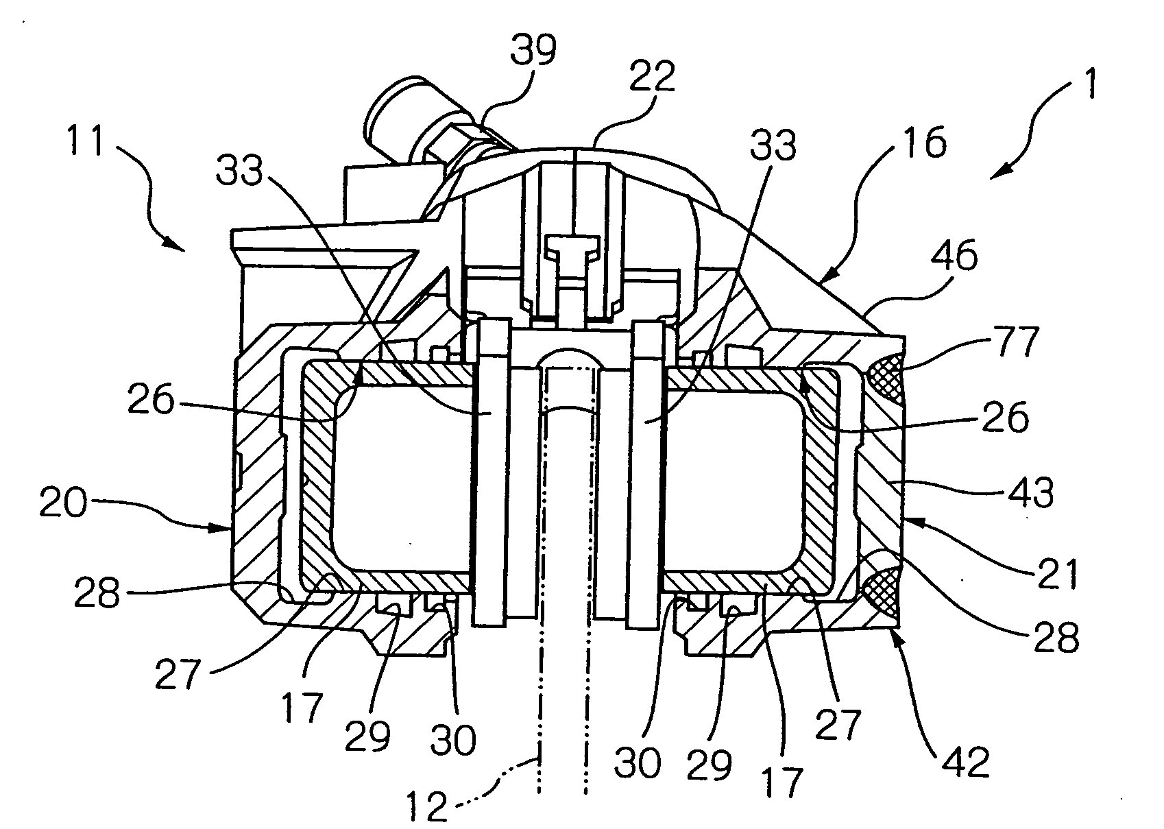
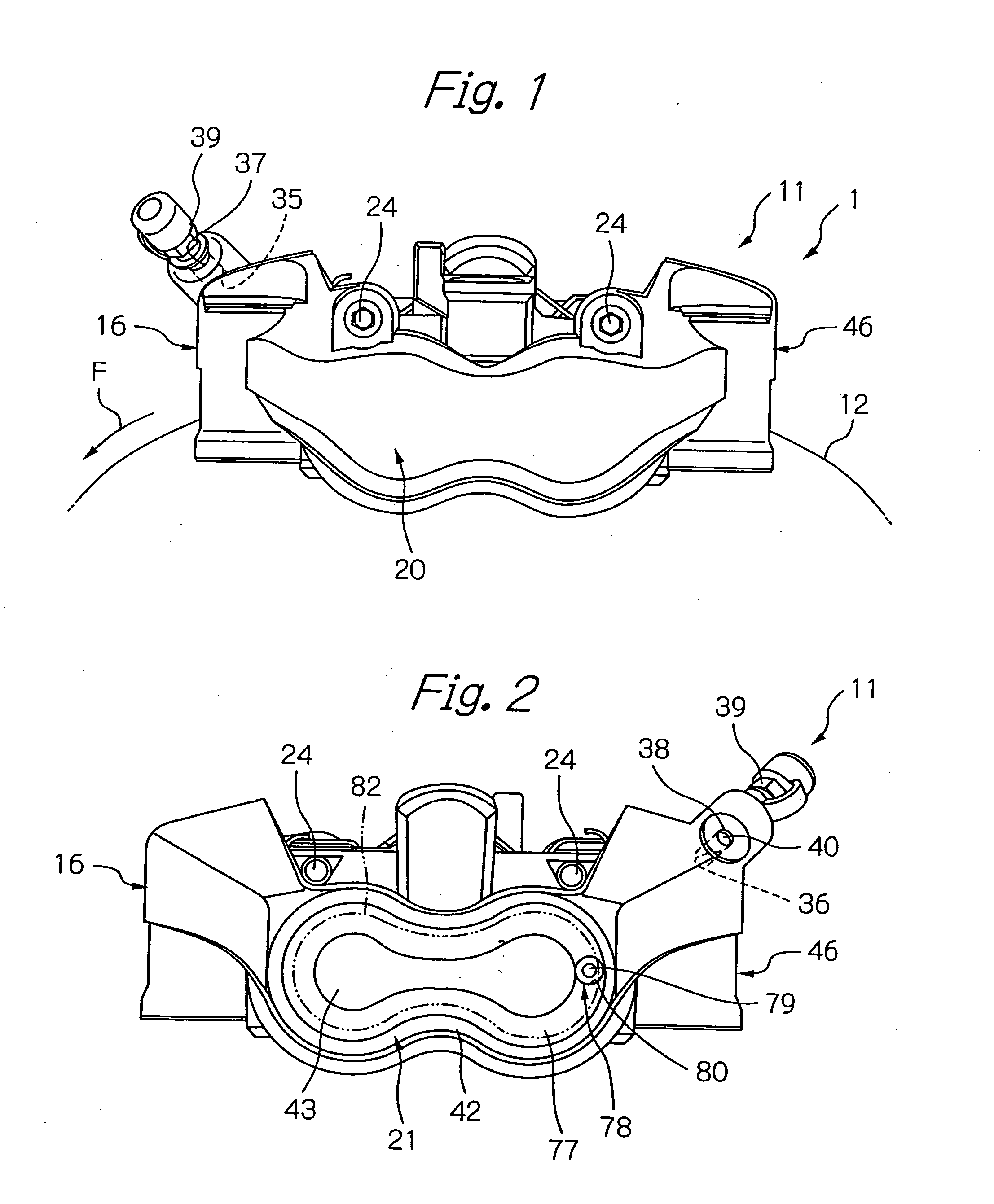
[0052]As an example of a cylinder apparatus, FIG. 1 shows a disk brake (a cylinder apparatus) 1 for a two-wheeled vehicle according to the first embodiment. The disk brake 1 has an opposed-piston caliper 11, shown in FIGS. 1 to 3, which comprises: a caliper body 16 attached to a non-rotatable portion of the vehicle so as to straddle the disk; and multiple pairs, specifically, two pairs of pistons 17 (in the cross sectional view of FIG. 3, only one pair of pistons 17 are shown), each pair of the pistons 17 being slidably disposed in the caliper body 16 such that the pistons 17 face each other through the disk 12. The description below is based on an installation state in which the disk brake 1 is installed in the vehicle, such that a radial direction of the disk 12 in the installation state is referred to as a disk radial direction; an axial direction of the disk 12 is referred to as a disk ...

second embodiment

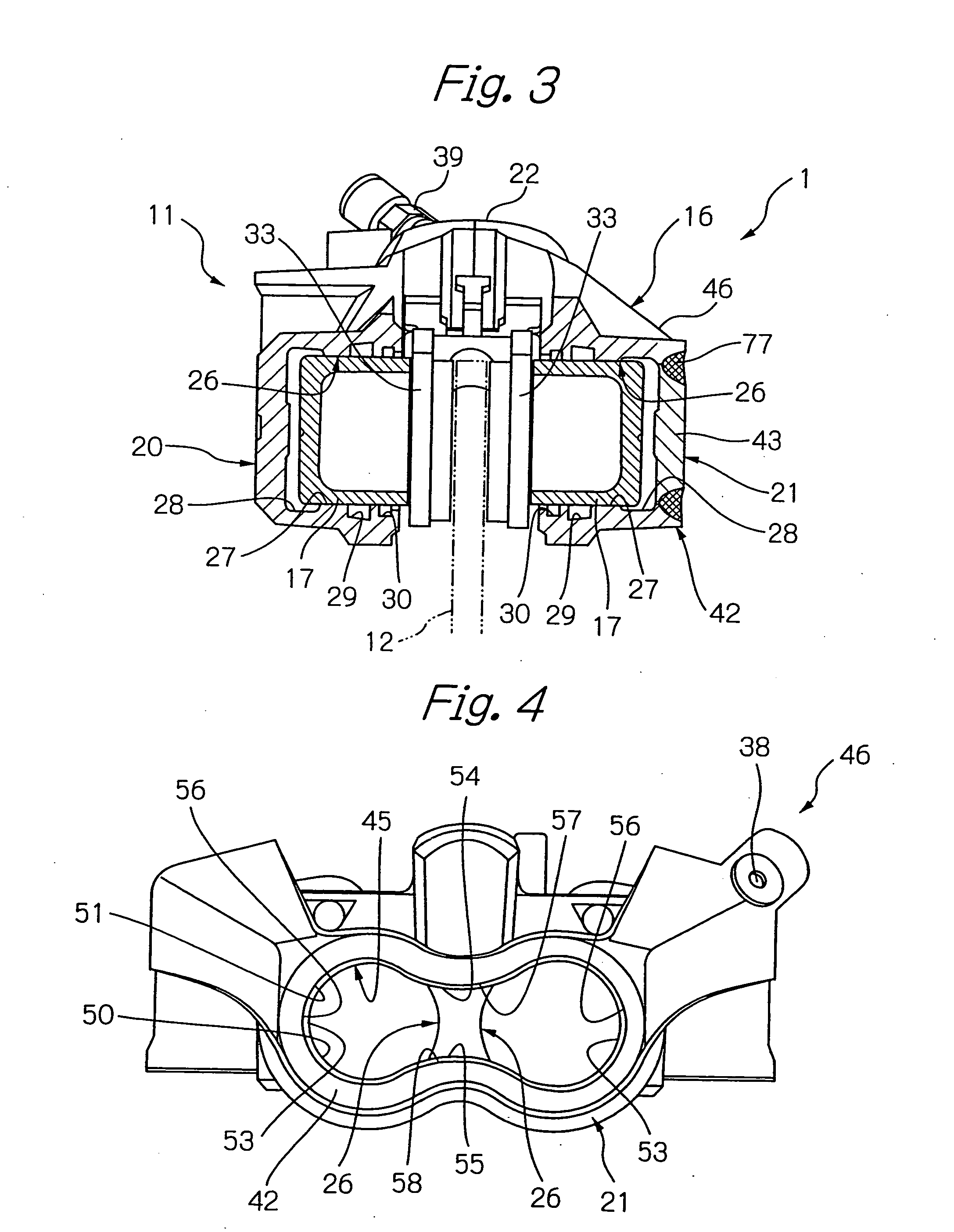
[0076]As shown in FIG. 8, in the second embodiment, when the covering member 43 is friction stir welded to the main part 46, the end position of the friction stir welding process where an impression of the welding tool 71 is left is displaced from the connection boundary 82 between the main open portion 50 and the main outer circumferential portion 60 where the main part 46 and the covering member 43 are in abutting contact with each other. In other words, the above-mentioned residual impression 78 is displaced from the connection boundary 82 between the main part 46 and the covering member 43. Specifically, the connecting portion 77, which is formed by friction stir welding in a closed loop, extends farther outward in a direction tangential to the bore 26, that is, toward the main part 46 to thereby form an extending portion 84, and the residual impression 78 that is located at an outside position that does not overlap with the closed-loop connecting portion 77 of the main part 46....

third embodiment

[0084] described above, the covering member 43 is friction stir welded to the main part 46 with the opening 45 being closed by the covering member 43 from inside the main part 46. This enables friction stir welding of the covering member 43 from outside the main part 46, while the covering member 43 is pressed against the main part 46 from inside the main part 46. In such a way, interference between a mechanism used for pressing the covering member 43 and that used for performing friction stir welding need not be taken into consideration. Further, since there is no possibility of the covering member 43 falling off outward of the main part 46, a strength of the main part 46 can be maintained.

[0085]Further, in the third embodiment, as shown in FIG. 9, the main part 46 (caliper 11) is provided with a pair of vehicle mounting portions 83 that each have a mounting hole 83a through which a mounting bolt (not shown) is inserted so as to radially mount the main part 46 onto the non-rotatabl...


PUM

PropertyMeasurementUnit
hydraulic pressureaaaaaaaaaa
inner diameteraaaaaaaaaa
melting pointaaaaaaaaaa

Abstract

A method of manufacturing a cylinder apparatus wherein although an opening of a cylinder body is closed by a covering member, processing and parts costs are reduced, fluid leakage is prevented, and the apparatus can be reduced in size. The cylinder apparatus includes a piston (17) which is caused to slidingly move in a bore (26) of a cylinder (21). The cylinder 21 includes a covering member (43) provided in a bottom portion (42) of the cylinder (21), and a cylinder body (46) having an opening that is closed by the covering member (43). The covering member (43) is friction stir welded to the cylinder body (46).

Description

[0001]This is a divisional application of Ser. No. 11 / 347,258, filed Feb. 6, 2006.BACKGROUND OF THE INVENTION[0002]The present invention relates to a cylinder apparatus and a disk brake.[0003]As an example of a cylinder apparatus in which a piston slidingly moves in a cylinder, there is known a disk brake wherein a braking operation is effected by causing a piston to slidingly move in a cylinder under application of a hydraulic pressure, whereby the piston is pushed outward relative to the cylinder against a brake pad, which in turn is brought into contact with a brake disk. To facilitate a process of forming an interior of a cylinder of such a disk brake, a cylinder may be divided into a covering member, which is provided in a bottom portion of the cylinder, and a cylinder body that has an opening which is closed by the covering member. In using this configuration, a process of forming an interior of the cylinder body is performed through the opening, after which the covering membe...

Claims


Application Information

Patent Timeline
Patent Type & Authority Applications(United States)
IPC IPC(8): F16D65/14B23P15/10
CPCB23K20/122F15B15/1438F16D2055/002Y10T29/49249F16D2125/04F16D2250/0076F16D2055/0091
Inventor SATO, TOMOJINANRI, KEISUKE
Owner HITACHI ASTEMO LTD
Why Eureka
Try Eureka