
Electrochemical Energy Generating Apparatus and Method of Driving the Same

a technology of electrochemical energy and generating apparatus, which is applied in the direction of electrochemical generators, fuel cells, reactant parameters control, etc., can solve the problem of crossover of direct methanol fuel supply type fuel cells, and achieve the effect of reducing fuel crossover, enhancing diffusibility and reactivity of fuel, and increasing energy density

Active Publication Date: 2008-11-20
MURATA MFG CO LTD
View PDF6 Cites 0 Cited by
  • Summary
  • Abstract
  • Description
  • Claims
  • Application Information

AI Technical Summary

Benefits of technology

[0012]Due to the crossover, the amount of methanol to be inherently used for power generation is reduced, and a reverse electromotive force is generated, leading to a lowering in cell voltage. As a result, the fuel cell is lowered in output density and energy density.
[0015]For example, there is a method in which a low-concentration aqueous methanol solution prepared through sufficient dilution of methanol with water is supplied to the fuel electrode. Although the crossover is alleviated by this method, the amount of methanol in the fuel cartridge is greatly reduced, spoiling the high energy density, which is the characteristic inherent in the fuel cell.
[0017]The present invention has been made in order to solve the above-mentioned problems. Accordingly, in this present invention, it is desirable to provide an electrochemical energy generating apparatus, and a method of driving the apparatus, by which crossover of fuel can be reduced and a high energy density can be realized.
[0021]According to the present invention, the fuel including an alcohol and substantially not containing water is supplied in a gaseous state to the side of the one of the electrodes of the electrochemical device by the fuel supplying unit. Therefore, it is possible to enhance the diffusibility and reactivity of the fuel, to reduce the crossover of fuel, and to obtain a higher energy density, as compared with the case of supplying the alcohol in a liquid state or the case of supplying an aqueous solution of the alcohol as a fuel. In short, the characteristics of the electrochemical energy generating apparatus can be enhanced.

Problems solved by technology

However, the direct methanol fuel supply type fuel cell is known to have the problem of crossover.

Method used


Image

  • Electrochemical Energy Generating Apparatus and Method of Driving the Same
  • Electrochemical Energy Generating Apparatus and Method of Driving the Same
  • Electrochemical Energy Generating Apparatus and Method of Driving the Same

Examples


example 1

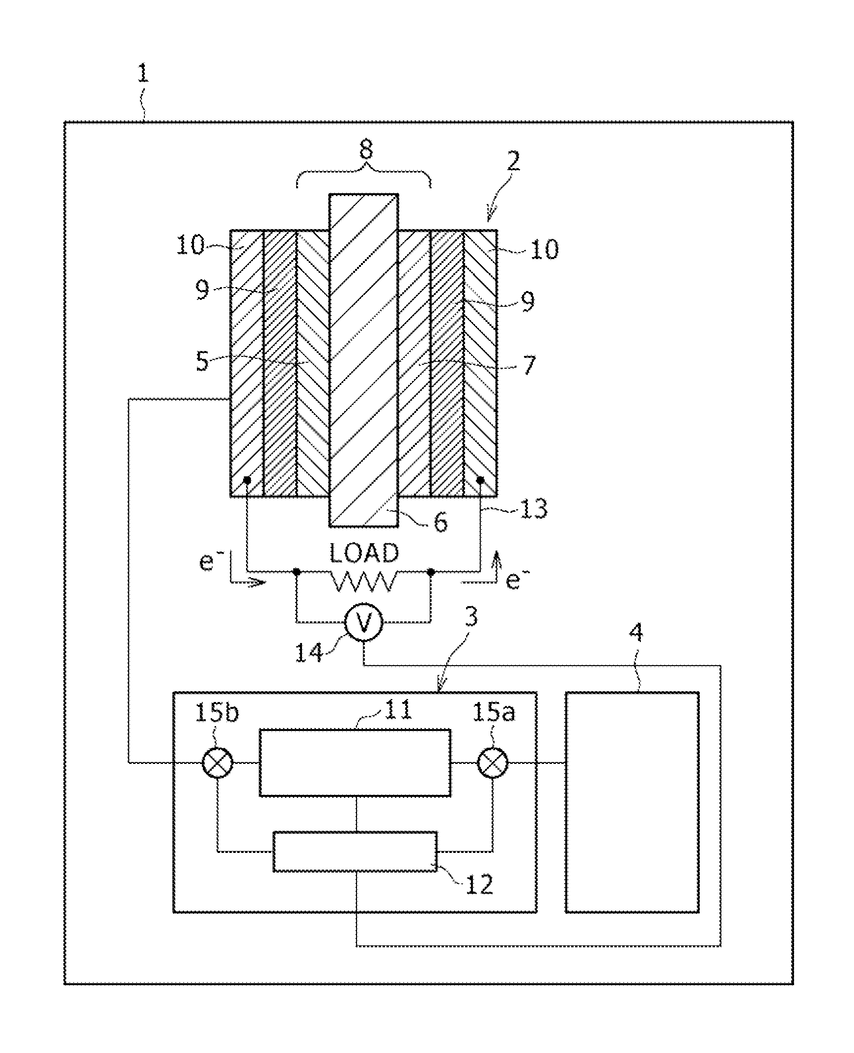
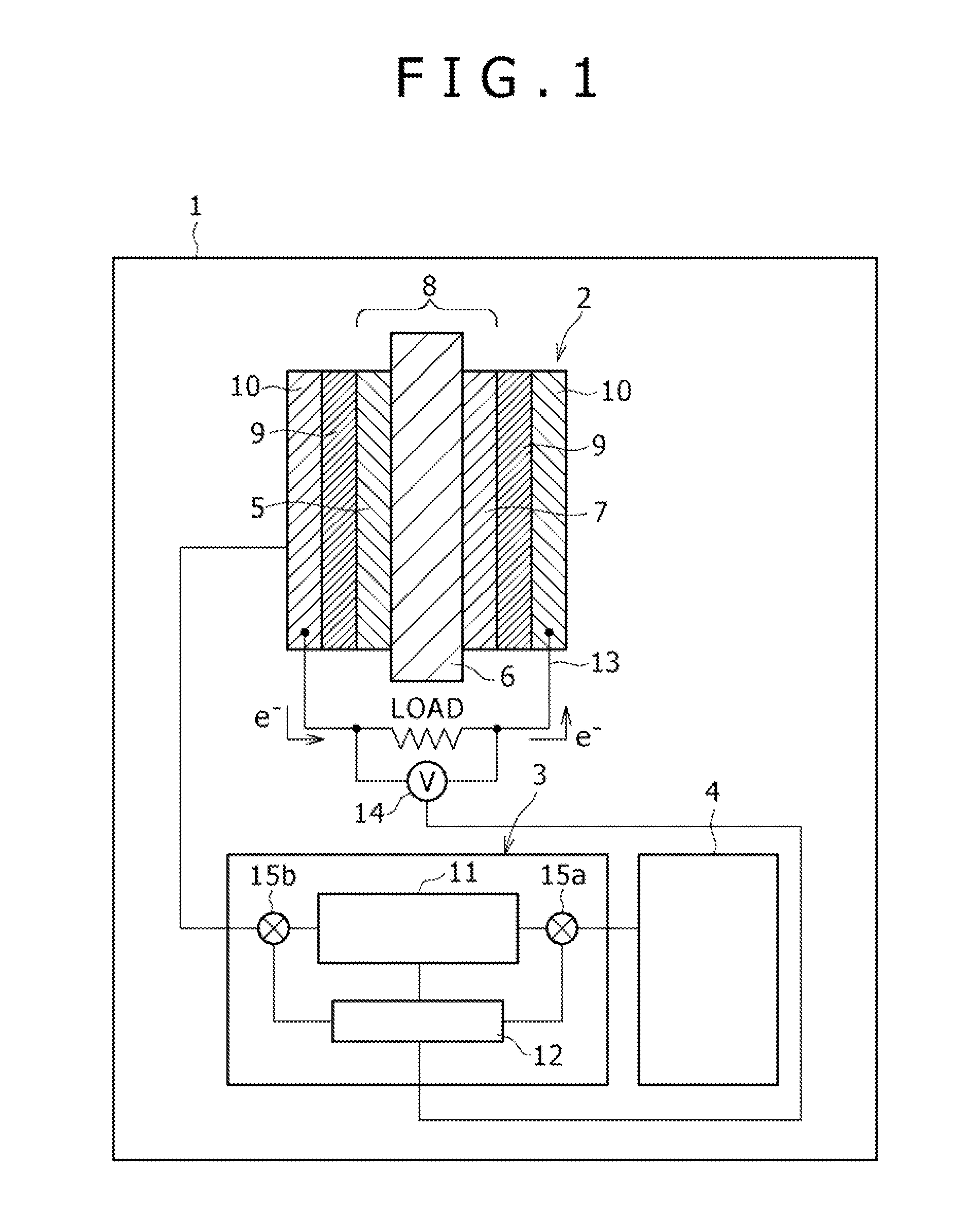
[0054]As the electrochemical device, a fuel cell 2 as shown in FIG. 1 was fabricated.

[0055]A fuel electrode 5 was prepared by mixing a catalyst, containing Pt and Ru in a predetermined ratio, with a dispersion of Nafion (registered trademark) in a predetermined ratio. In addition, an air electrode 7 was prepared by a catalyst, having Pt carried on carbon powder, with a dispersion of Nafion in a predetermined ratio.

[0056]Next, the fuel electrode 5 and the air electrode 7 prepared as above were hot pressed together with an about 90 μm-thick polymer solid electrolyte membrane (Nafion 1135 (registered trademark), a product by du Pont) under the conditions of 150° C. and 0.2 kN for 10 min, to prepare an MEA 8.

[0057]The MEA 8 was sandwiched by a 280 μm-thick carbon paper (product code: HGP-H-090, a product by Toray Industries, Inc.) and a titanium mesh, to fabricate the fuel cell 2. Here, the carbon paper corresponds to the diffusion layer 9, and the titanium mesh corresponds to the curre...

example 2

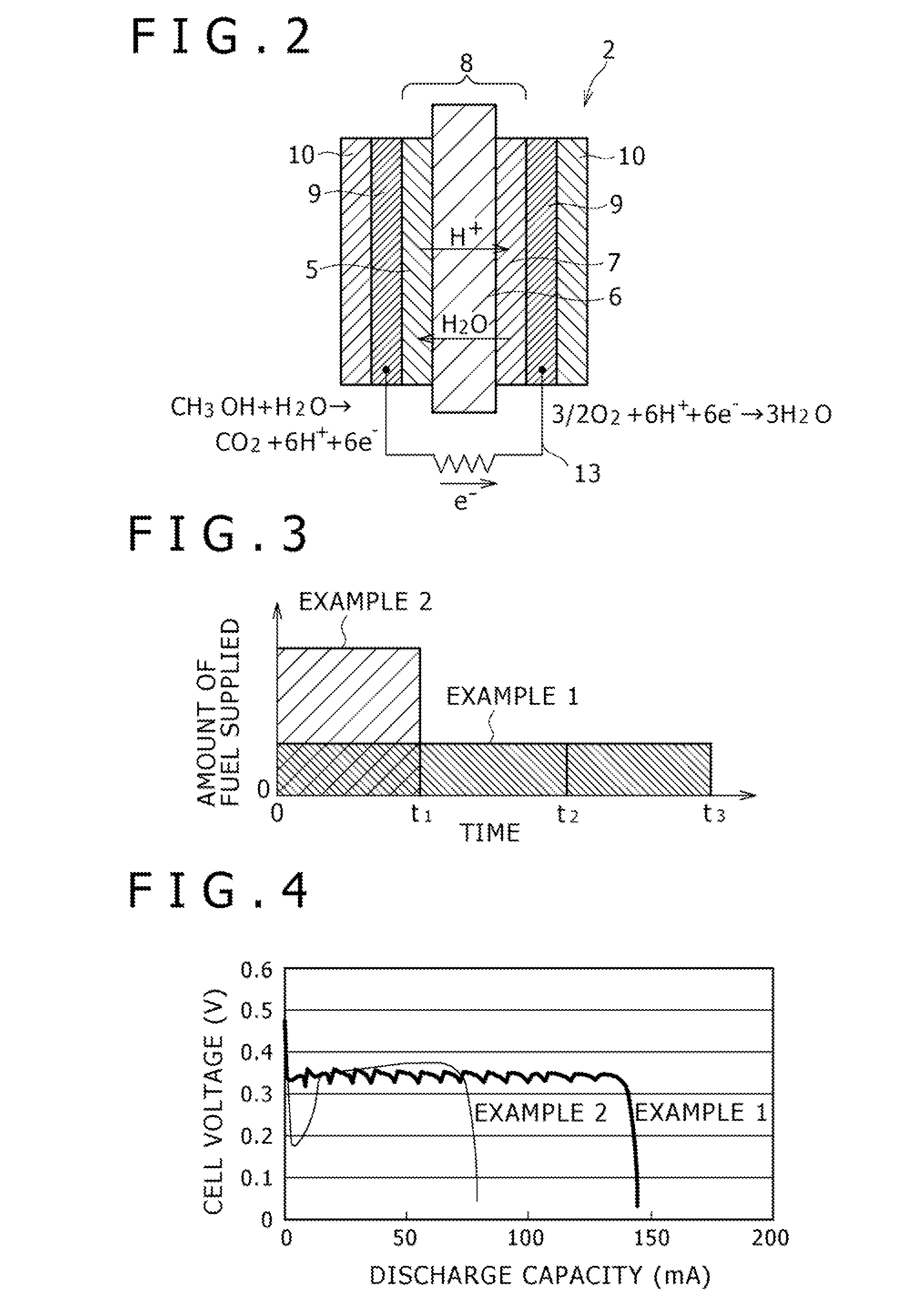
[0061]A fuel cell system 1 was fabricated in the same manner as in Example 1, except that the same total amount (50 μl) of methanol as used in Example 1 was supplied to the filter paper at a time, without controlling the amount of methanol supplied to the filter paper (fuel evaporating section 11) by utilizing a syringe, as shown in FIG. 3.

[0062]Incidentally, in Examples 1 and 2, only the evaporated methanol was supplied to the fuel electrode 5, and the water necessary for consumption of methanol was not supplied to the fuel cell 5 at all.

[0063]Then, characteristics of the fuel cell systems fabricated in Examples 1 and 2 were evaluated.

[0064]The fuel cell was connected to an electrochemical measuring instrument (product name: MULTISTAT 1480, a product by Solartron), a control was made such that the current flowing in the fuel cell would be constant (100 mA), and the cell voltage of the fuel cell was serially read. The results are collectively shown in FIG. 4.

example 3

[0073]A fuel cell system 1 was fabricated in the same manner as in Example 1, except that the system was so configured that methanol (20 μl) was supplied in a gaseous state.


PUM

PropertyMeasurementUnit
electrochemical energyaaaaaaaaaa
energy densityaaaaaaaaaa
operating temperaturesaaaaaaaaaa

Abstract

An electrochemical energy generating apparatus with which the crossover of a fuel can be suppressed and a method of driving the apparatus are disclosed. The electrochemical energy generating apparatus (e.g., a fuel cell system) 1 includes an electrochemical device (fuel cell) 2 which has an electrolyte membrane 6 clamped between opposed electrodes 5 and 7 and which generates electrochemical energy by a reaction of an alcohol with water at one (fuel electrode) 5 of the electrodes 5, 7, and a fuel evaporating section 11 by which a fuel including said alcohol and substantially not containing water is supplied in a gaseous state to the side of the one 5 of the electrodes 5, 7 of the electrochemical device 5. The method of driving the electrochemical energy generating apparatus 1 includes supplying the fuel in the gaseous state to the one 5 of the electrodes 5, 7 by the fuel evaporating section 11.

Description

TECHNICAL FIELD[0001]The present invention relates to an electrochemical energy generating apparatus and a method of driving the apparatus.BACKGROUND ART[0002]Because of the high energy density of fuel, fuel cells are expected as next-generation batteries for not only electric vehicles but also mobile apparatuses such as notebook type personal computers and mobile phones, and research and development thereof are being vigorously conducted in many research institutes and companies.[0003]Especially, the so-called polymer solid electrolyte type fuel cells, in which a polymer solid electrolyte is used to form an ion-permeable electrolyte membrane, are considered to be suitable for application to batteries for electric vehicles and mobile apparatuses, because of their comparatively low operating temperatures.[0004]The polymer solid electrolyte type fuel cells generally have a configuration in which electrodes are provided on both sides of an ion-permeable electrolyte membrane.[0005]In ad...

Claims


Application Information

Patent Timeline
Patent Type & Authority Applications(United States)
IPC IPC(8): H01M8/04H01M8/18
CPCH01M8/04201H01M8/04261H01M8/0606H01M8/1009Y02E60/522H01M8/04197Y02E60/50H01M8/04H01M8/10
Inventor UESAKA, SHINICHIARAKI, NORITOSHI
Owner MURATA MFG CO LTD
Learn More