
Photolytic Polymer Surface Modification

a surface modification and polymer technology, applied in the field of photolysis polymer surface modification, can solve the problems of poor mechanical integrity, limited utility as a device material, lack of robust surface modification techniques, etc., and achieve the effect of high glass transition temperature and low shrinkage stress

Inactive Publication Date: 2008-11-06
UNIV OF COLORADO THE REGENTS OF
View PDF0 Cites 15 Cited by
  • Summary
  • Abstract
  • Description
  • Claims
  • Application Information

AI Technical Summary

Benefits of technology

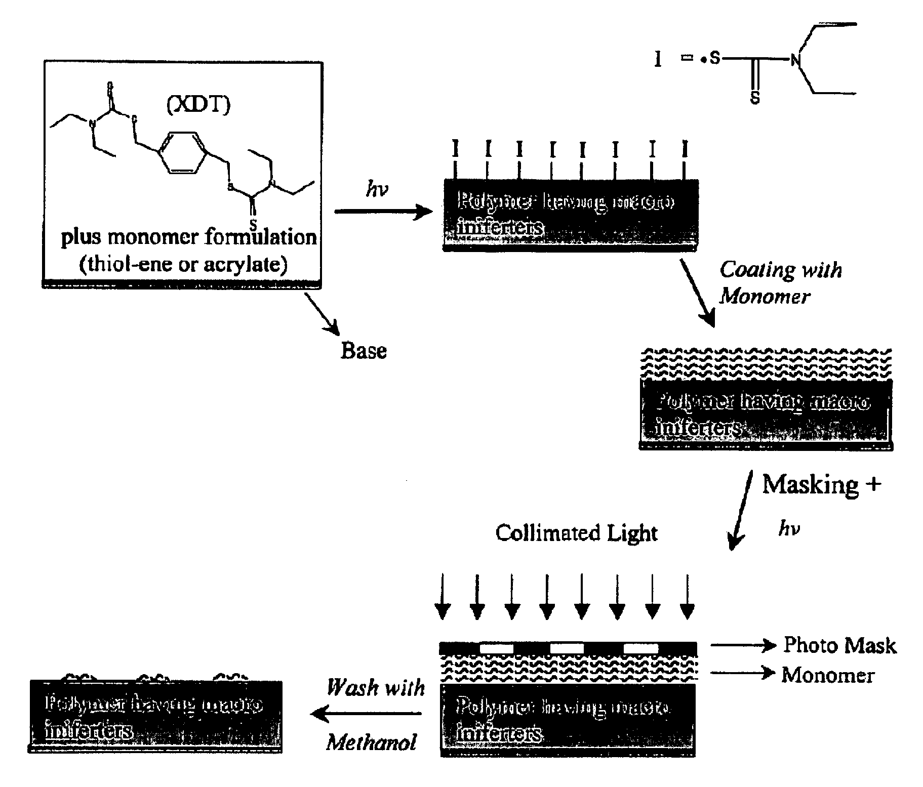
[0015]In some methods of the present invention, the monomer mixture used to produce the polymer further comprises a photoiniferter. This allows the polymer surface to comprise photoiniferter moieties, thus allowing modification of the polymer surface using a photolithography process.
[0021]Some embodiments of the present invention provide a homogeneous polymer with high glass transition temperature and low shrinkage stress.
[0024]Another aspect of the present invention provides a method for producing polymers, preferably homogeneous polymers, with low shrinkage stress and high glass transition temperatures.

Problems solved by technology

While these techniques have proven useful in a number of microfluidics applications, each have its own short comings.
For example, soft lithography techniques typically utilize PDMS rubber, which has limited utility as a device material, exhibits poor mechanical integrity with solvent swelling of up to 100%, little resistance to diffusion, and lacks robust surface modification techniques.
The lack of integrity in these polymer matrices is unfortunate, since the effectiveness of a microdevice relies heavily on materials and surface properties of the device.
Such grafts may be unstable under high shear forces or other adverse chemical and physical conditions.
Surface modification via coupling reactions (grafting-to) has several limitations, including incomplete surface coverage, diffusion limitations of the polymers to the surface, and island formation due to steric crowding of the reactive sites by the already grafted polymers.
In addition, some of the available polymerization methods are oxygen sensitive (e.g., polymerization reaction is inhibited by oxygen) and achieve low rate of conversion.
It is believed that some of these limitations of conventional monomeric mixtures and / or photopolymerization methods are primary due to the self-limiting nature of their reaction mechanisms.

Method used


Image

  • Photolytic Polymer Surface Modification
  • Photolytic Polymer Surface Modification
  • Photolytic Polymer Surface Modification

Examples


example 1

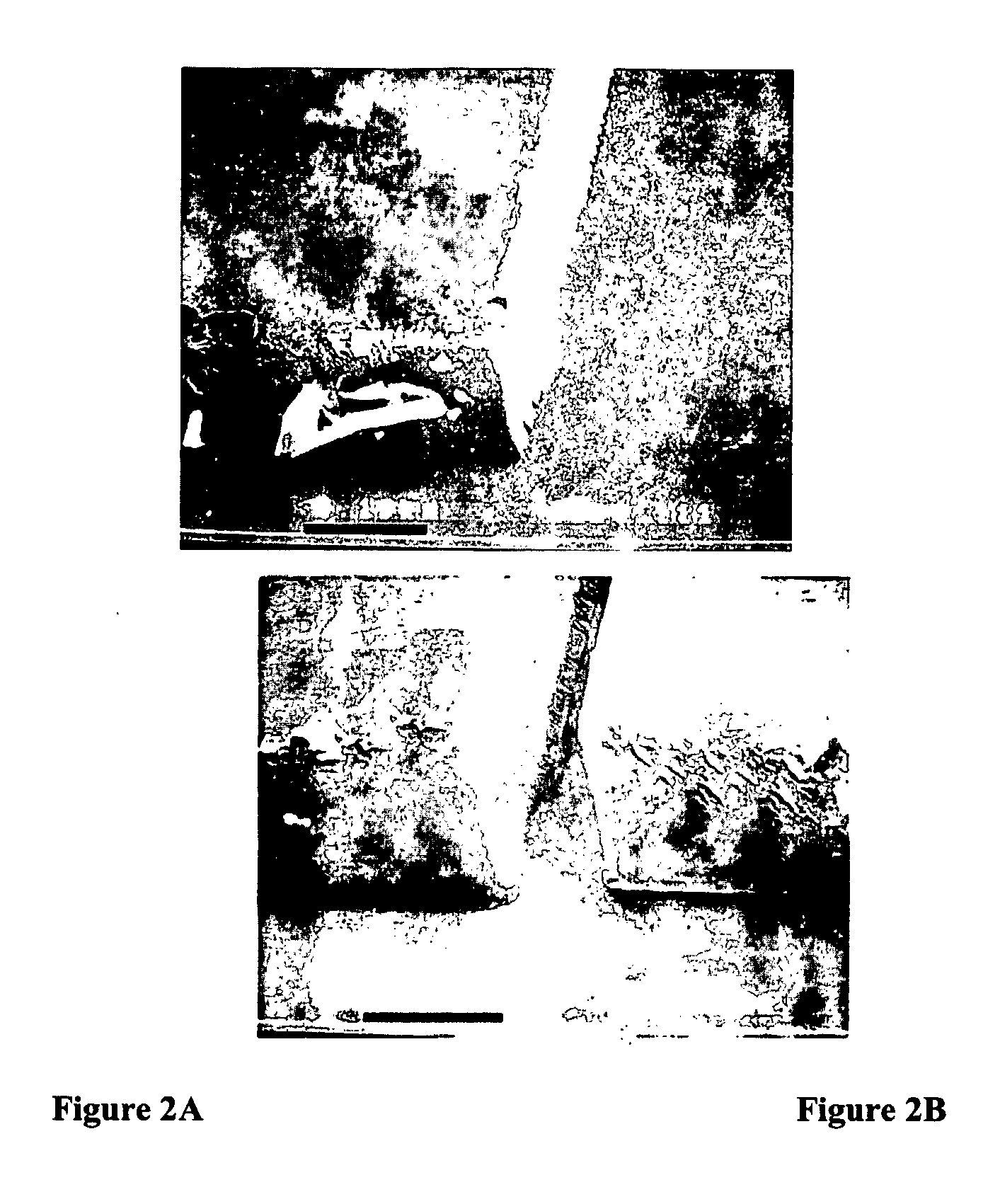
[0096]This example illustrates a comparative photopatterning study of polymers derived from a mixture of monomers that does not contain any thiol monomer and polymers derived from a mixture of monomers that comprises a thiol monomer in accordance with the present invention.

[0097]Two-dimensional polymeric structures formed from a urethane acrylate monomer formulation are shown in FIG. 2. The formulation for FIG. 2 consists of a 50:50 mixture of Ebecryl 4827 aromatic urethane diacrylate (Surface Specialties, UCB) and SR272* triethylene glycol diacrylate (Sartomer) with 1.5 wt % Irgacure 184 (Ciba Geigy) and 1.0 wt % tetraethylthiuram disulfide (TED) (Aldrich). It is believed that the structures in FIG. 2 are ridged due to shrinkage stress and bowed outwards at the base of the structures. These features are common in photopatterned structures derived from methacrylate monomer systems due to shrinkage stress and oxygen inhibition.

[0098]Polymerization of thiol monomer and acrylate monome...

example 2

Formation of Reactive Substrates

Thiol-Olefin Polymers Versus Acrylate Polymers

[0101]Experiments were conducted to investigate the curing kinetics of typical thiol-olefin polymers in the presence of photoiniferters and compared with those of typical acrylate and methacrylate polymerization rate under similar conditions. FIG. 5 shows the rate of various polymerization reactions in the presence of 0.5 wt % XDT, and at an irradiation intensity of 5 mW / cm2. In FIG. 5, (- -) shows the polymerization rate of pentaerythritol tetra-(3-mercaptopropionate)-triethylene glycol divinyl ether mixture; (——) shows the polymerization rate of pentaerythritol tetra-(3-mercaptopropionate)-Vectomer 5015 vinyl ether mixture; (∘) shows the polymerization rate of triethyleneglycol diaciylate; and (□) shows the polymerization rate of triethyleneglycol dimethacrylate.

[0102]As shown in FIG. 5, in the presence of XDT, the polymerization rate of mixtures comprising a thiol monomer was one to two orders of magnit...

example 3

[0103]Polymerization rate of monomer compositions of the present invention are significantly less sensitive to oxygen inhibition. FIG. 6 is a graph showing the conversion (i.e., polymerization) versus time profiles for thiol-DVE3 and TEGDA systems containing 0.5 wt % XDT in the presence of air. Both samples were polymerized at an intensity of 5 mW / cm2. In FIG. 6, (—) shows the rate of thiol-DVE3 polymerization and (——) shows the rate of TEGDA polymerization. As can be seen, while the thiol-olefin monomer composition cures rapidly even in the presence of air, TEGDA shows significantly reduced conversion under these conditions.


PUM

PropertyMeasurementUnit
glass transition temperatureaaaaaaaaaa
heightaaaaaaaaaa

Abstract

The present invention provides a method for modifying a surface of a polymer derived from a mixture comprising a thiol monomer and an olefinic monomer. The method comprises exposing at least a portion of the polymer surface to electromagnetic radiation of sufficient energy to modify the polymer surface. The present invention also provides a polymer derived from polymerizing a mixture of monomers comprising a thiol monomer, an olefinic monomer, and an iniferter.

Description

CROSS-REFERENCE TO RELATED APPLICATIONS[0001]This application claims the priority benefit of U.S. Provisional Application No. 60 / 637,111, filed Dec. 16, 2004, which is incorporated herein by reference in its entirety.STATEMENT REGARDING FEDERALLY SPONSORED RESEARCH[0002]The U.S. Government has a paid-up license in this invention and the right in limited circumstances to require the patent owner to license others on reasonable terms as provided for by the terms of Tie Grant No. EEC-0120943 awarded by the National Science Foundation.FIELD OF THE INVENTION[0003]The present invention relates to a method for modifying a surface of a polymer derived from a mixture comprising a thiol monomer and an olefinic monomer. The present invention also relates to a polymer derived from polymerizing a mixture of monomers comprising a thiol monomer, an olefinic monomer, and optionally an iniferter.BACKGROUND OF THE INVENTION[0004]Conventional techniques for microdevice fabrication on glass and silicon...

Claims


Application Information

Patent Timeline
Patent Type & Authority Applications(United States)
IPC IPC(8): B32B3/30C08J3/28C08G75/04
CPCC08F283/00C08F291/00Y10T428/2457C08J7/12C08J2341/00C08F291/18
Inventor BOWMAN, CHRISTOPHER N.REDDY, SIRISHCRAMER, NEILSEBRA, ROBERT P.LU, HUI
Owner UNIV OF COLORADO THE REGENTS OF
Learn More